
Production method of photoreaction product sheet and apparatus for the same

a technology of photoreaction and product sheet, which is applied in the direction of chemistry apparatus and processes, film/foil adhesives, coatings, etc., can solve the problems of inconvenience of installing a plurality of kinds of irradiation units, long production lines, and conventional methods, so as to reduce the number of light irradiators such as lamps and fluorescent tubes, the apparatus configuration is simplified, and the friction of an individual conveying roller can be reduced.

Inactive Publication Date: 2014-05-29
NITTO DENKO CORP
View PDF0 Cites 0 Cited by
  • Summary
  • Abstract
  • Description
  • Claims
  • Application Information

AI Technical Summary

Benefits of technology

The present invention is about a method and apparatus for producing a photoreaction product sheet. The technical effect of the invention is that even as the apparatus is simplified, a high-quality photoreaction product sheet can be efficiently produced. The support is turned around while keeping contact with multiple conveying rollers, reducing friction and tension, preventing folding crease. The light emitted towards the supports with a photoreactive composition layer can photopolymerize all compositions, efficiently utilizing light. The light transmitted through a light-transmitting release liner acts on the photoreactive composition layer while shielding unreacted monomer from contamination and reducing illuminance. The method and apparatus allow for a reduction in number of light irradiators and a high-quality photoreaction product sheet.

Problems solved by technology

However, the conventional methods have the following problems.
Accordingly, not only the production line becomes long but also there occurs an inconvenience that a plurality of kinds of irradiation units must be installed.
Furthermore, in the method used in Patent Document 5, a folding crease may occur during the turnaround when the photoreaction product sheet is turned around.
That is, there is a problem that the produced photoreaction product sheet may be dealt with as an appearance failure due to the folding crease.

Method used


Image

  • Production method of photoreaction product sheet and apparatus for the same
  • Production method of photoreaction product sheet and apparatus for the same
  • Production method of photoreaction product sheet and apparatus for the same

Examples


first embodiment

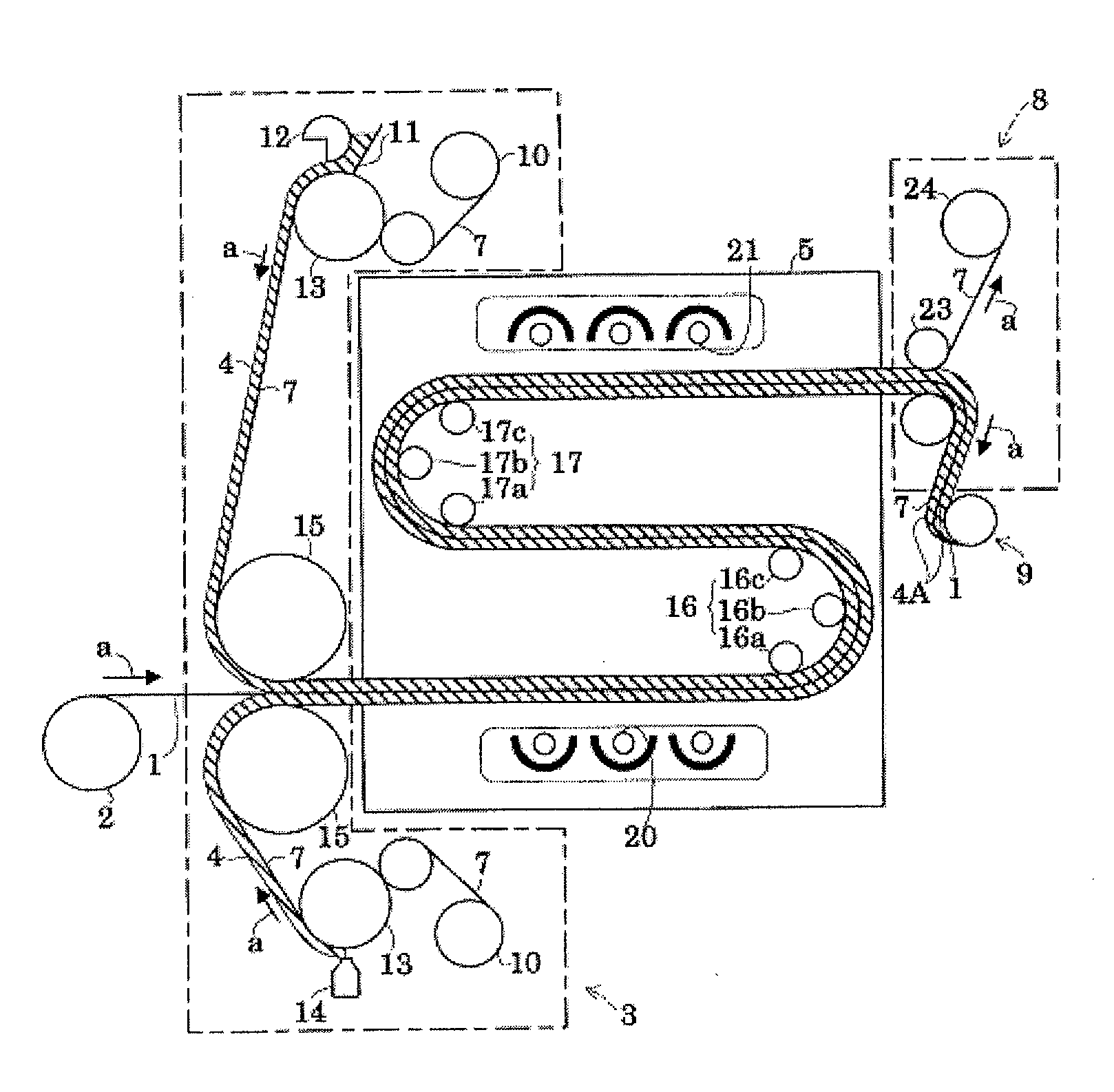
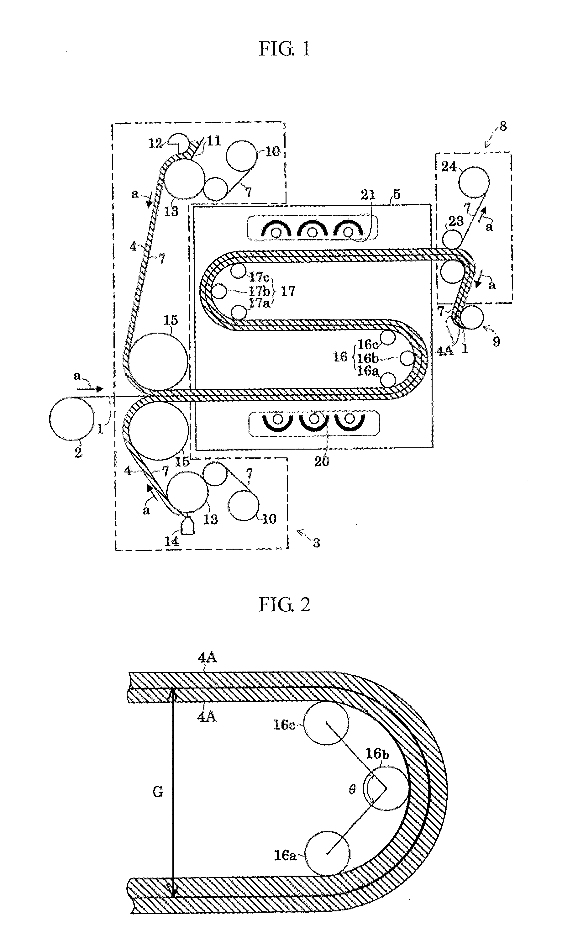
[0055]The production apparatus of a photoreaction product sheet according to this Embodiment consists of, as shown in FIG. 1, a support feed roll 2 of unrolling and feeding a sheet-shaped, tape-shaped or film-shaped support (base material) 1; a coating section 3 of applying (coating) a photopolymerizable composition (hereinafter, sometimes referred to as “photopolymerizable composition 4”) to a predetermined thickness so as to form a photopolymerizable composition layer 4 on the support 1 unrolled from the support feed roll 2; a first irradiation chamber 5 of irradiating the photopolymerizable composition 4 applied to the support 1 with light; a separation section 8 of separating the later-described light-transmitting release liner 7 from the laminate of the support 1 and a pressure-sensitive adhesive layer 4A formed thereon, obtained from the photopolymerizable composition layer 4 by a photopolymerization reaction in the course of being conveyed in the first irradiation chamber 5; ...

second embodiment

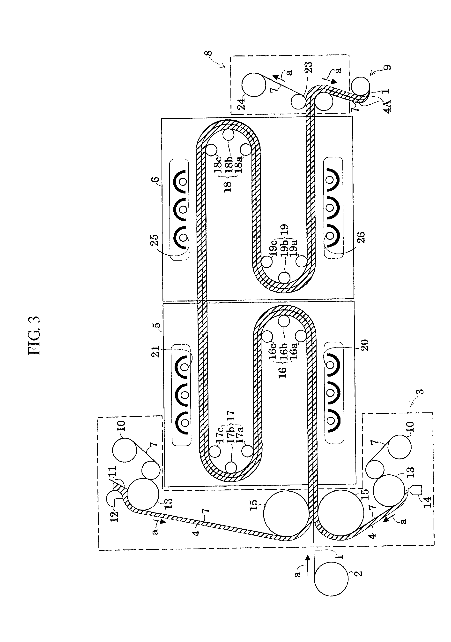
[0088]In this Embodiment, the apparatus differs from that of the First Embodiment in that a second irradiation chamber 6 adjacent to the first irradiation chamber 5 is provided. Accordingly, while only assigning the same reference numeral or sign to the same constituent element, the different constituent element is described in detail below.

[0089]In the second irradiation chamber 6, as shown in FIG. 3, the support 1 conveying path is formed in line-symmetrical manner with respect to adjacent wall parts of the first irradiation chamber 5 and the second irradiation chamber 6. That is, the second irradiation chamber 6 is provided with a third turnaround mechanism 18 of turning around the support 1 to move the support 1 in the direction opposite the transferring direction of the support 1 conveyed from the first irradiation chamber 5; a fourth turnaround mechanism 19 of turning around the support 1 to move the support 1 in the direction opposite the transferring direction of the support...

specific example

[0093]In the photopolymerization, a 38-μm polyethylene film subjected to a silicone treatment was used as the light-transmitting release liner 7 of shielding the short-wavelength light.

[0094]The photopolymerizable composition was prepared as follows. Into a four-neck flask were charged 90 parts by weight of 2-ethylhexyl acrylate (2EHA) as the principal monomer with the main component being an alkyl acrylate monomer, 10 parts by weight of an acrylic acid (AA) as the polar group-containing copolymerizable monomer, and 0.05 parts by weight of 2,2-dimethoxy-2-phenylacetophenone as the photopolymerization initiator, and the mixture was exposed to an ultraviolet ray in a nitrogen atmosphere to obtain a partially photopolymerized syrup. With 100 parts by weight of this partially polymerized syrup, 0.04 parts by weight of 1,6-hexanediol diacrylate as the crosslinking agent was uniformly mixed to obtain a photopolymerizable composition.


PUM

PropertyMeasurementUnit
Angleaaaaaaaaaa
Angleaaaaaaaaaa
Diameteraaaaaaaaaa

Abstract

The present invention relates to a method in which: a photoreactive composition layer is formed on a support while conveying the support in one direction, the support is turned around at least once so that the support before turnaround faces the support after turnaround by conveying the support in the direction opposite the foregoing one direction to make a conveying route of the support multistage traveling, and in the course of multistage traveling, the support is turned around while keeping contact with three or more conveying rollers at least during the first turnaround, and light is emitted toward the support from a light irradiator to cause photopolymerization of the photoreactive composition layer formed on the support.

Description

TECHNICAL FIELD[0001]The present invention relates to a production method of a photoreaction product sheet, containing irradiating a photoreactive composition layer formed on a sheet-shaped, tape-shaped or film-shaped support with light to cause a photoreaction of the photoreactive composition layer to obtain a photoreaction product layer; and an apparatus for the same.BACKGROUND ART[0002]Conventionally, there is known a method for producing a photoreaction product sheet by coating a photoreactive composition layer to an appropriate thickness on a support such as film-shaped support and reacting (polymerizing) the coated photoreactive composition layer by the irradiation with light to form a photoreaction product layer. Examples of the photoreaction product sheet includes a pressure-sensitive adhesive sheet where the photoreactive composition layer is a photopolymerizable composition layer and a pressure-sensitive adhesive layer is formed by polymerizing the formed photoreactive com...

Claims


Application Information

Patent Timeline
IPC IPC(8): C09J7/02C08J5/18C09J7/38
CPCB29C35/0888B29C35/10B29C2035/0827C09J7/38B32B38/00B32B37/00C08J5/18
Inventor AKIYAMA, JUNNAKASHIMA, TOORU
Owner NITTO DENKO CORP
Learn More