
Display panel and display device having the same

a display panel and display panel technology, applied in non-linear optics, instruments, optics, etc., can solve the problems of increased manufacturing costs and decreased brightness, and achieve the effects of reducing manufacturing costs, reducing optical materials, and increasing brightness of display panels

Inactive Publication Date: 2014-05-29
SAMSUNG DISPLAY CO LTD
View PDF9 Cites 60 Cited by
  • Summary
  • Abstract
  • Description
  • Claims
  • Application Information

AI Technical Summary

Benefits of technology

This patent is about a display panel that can increase brightness and prevent a reddish phenomenon in the column direction of the panel. The panel uses a reflection polarizer as the first polarizer, which reduces optical materials and increases brightness without the need for a film to increase brightness. Additionally, a viewing angle control layer is included to decrease the viewing angle at the column direction of the panel and prevent the reddish phenomenon. These features make the display panel more efficient and cost-effective.

Problems solved by technology

However, because the display panel includes different type of polarizers, the brightness may be decreased and the manufacturing costs associated therewith may be increased.

Method used


Image

  • Display panel and display device having the same
  • Display panel and display device having the same
  • Display panel and display device having the same

Examples


Embodiment Construction

[0045]Hereinafter, example embodiments will be explained in detail with reference to the accompanying drawings.

[0046]In the drawings, the thickness of layers, films, panels, regions, etc., may be exaggerated for clarity. Like reference numerals designate like elements throughout the specification. It will be understood that when an element such as a layer, film, region, or substrate is referred to as being “on” another element, it can be directly on the other element or intervening elements may also be present.

[0047]As used herein, the singular forms, “a”, “an”, and “the” are intended to include plural forms as well, unless the context clearly indicates otherwise.

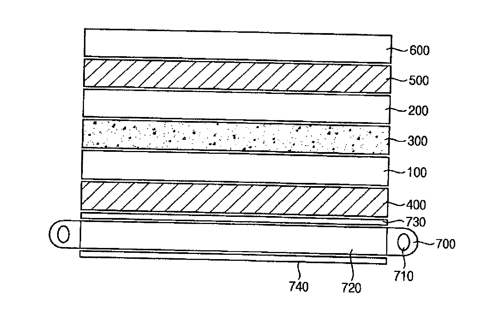
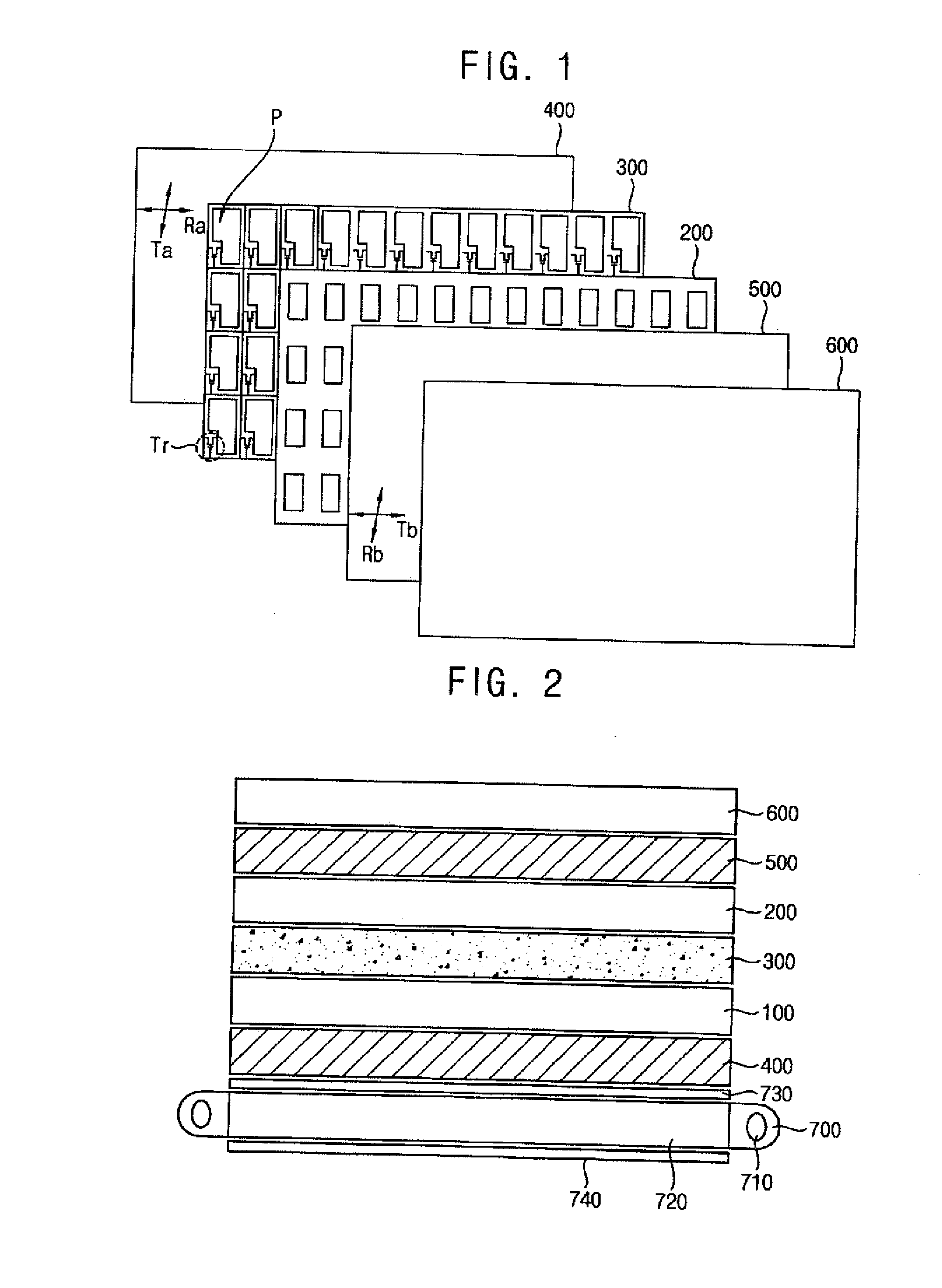
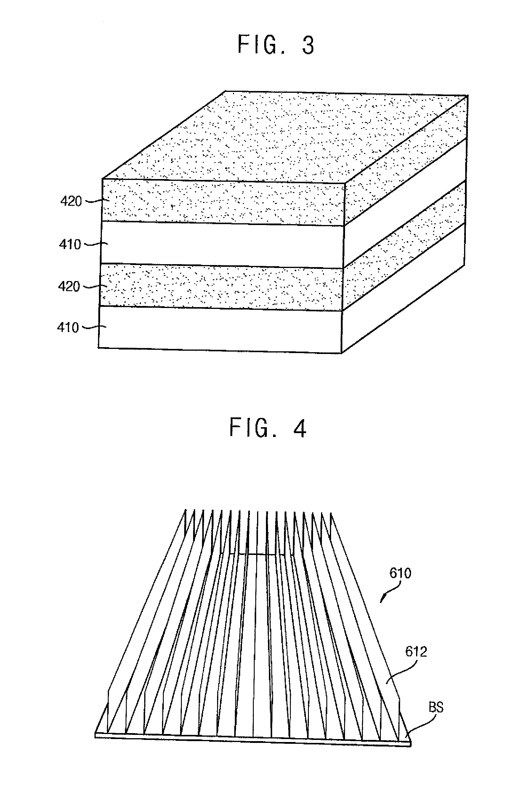
[0048]FIG. 1 is a plan view illustrating a display panel in accordance with an example embodiment. FIG. 2 is a cross-sectional view illustrating a display device including the display panel of FIG. 1. FIG. 3 is a perspective view illustrating a reflection polarizer in the display panel of FIG. 1.

[0049]Referring to FIGS. 1 t...


PUM

PropertyMeasurementUnit
viewing angleaaaaaaaaaa
angleaaaaaaaaaa
optical axisaaaaaaaaaa

Abstract

A display panel includes a first substrate, a second substrate, a liquid crystal layer, a first polarizer, a second polarizer and a viewing angle control layer. The second substrate faces the first substrate. A liquid crystal layer is disposed between the first substrate and the second substrate. A first polarizer is disposed on a lower surface of the first substrate and includes a first polarizing layer and a second polarizing layer stacked on each other. A second polarizer is disposed on an upper surface of the second substrate. A viewing angle control layer is disposed on the first polarizer and is configured to control a viewing angle of a column direction of the display panel.

Description

[0001]This application claims priority to Korean Patent Application No. 10-2012-0133365, filed on Nov. 23, 2012, the disclosure of which is hereby incorporated by reference herein in its entirety.TECHNICAL FIELD[0002]Example embodiments relate to a display panel and a display device having the same. More particularly, example embodiments relate to a display panel including a viewing angle control layer and a reflective polarizer, and a display device having the same.DISCUSSION OF THE RELATED ART[0003]A Liquid Crystal Display LCD device is one type of flat display device. The LCD device is a display device that applies voltages to specific molecules of liquid crystal to convert arrangements of the molecules and change an optical property of the liquid crystal cell such as, for example, a birefringence, an optical activity, a dichroism, a light scattering, etc, to display an image.[0004]Generally, the display panel includes a liquid crystal layer disposed between two substrates. A liq...

Claims


Application Information

Patent Timeline
Patent Type & Authority Applications(United States)
IPC IPC(8): G02F1/1335
CPCG02F1/133524G02F1/133536G02F1/133531G02F1/1335
Inventor KIM, SANG-JAEKI, BOO-KANKIM, JI-HYEDO, HEE-WOOKPARK, JAE-WONSUH, DUCK-JONGLEE, JUNG-HUNLEE, HYOUNG-JOOCHO, SEON-AHHONG, HYO-SUNG
Owner SAMSUNG DISPLAY CO LTD
Learn More