
Covered housing

a technology of covering and fabric, applied in the field of covering housing, can solve the problems of not working in the housing, difficult to create tension in the fabric vertically and horizontally around the cylindrical shaped component,

Active Publication Date: 2014-05-22
LOGITECH EURO SA
View PDF4 Cites 24 Cited by
  • Summary
  • Abstract
  • Description
  • Claims
  • Application Information

AI Technical Summary

Benefits of technology

The invention provides a way to securely hold fabric in place on a cylindrical shaped component, such as a speaker housing. The tension is controlled in both vertical and horizontal directions, which makes it difficult to pull the fabric off. A sock assembly is used to secure the fabric, which can be opened and controlled at both ends. This allows for additional features or controls, such as buttons, to be added to the speaker housing. Overall, the invention solves a problem where it was difficult to securely hold fabric in place on a cylindrical shaped component.

Problems solved by technology

There are many challenges for assembling fabric to a unique shaped housing.
If using a unique speaker housing shape, such as a cylinder shape, it is difficult to create tension in the fabric both vertically and horizontally around the cylindrical shaped component after the fabric is assembled to a cylindrical shape.
Accordingly, a traditional sock assembly where a fabric sock that is open on both ends is slipped over a rectangular or cylinder housing would not work because the tension along the length of the sock cannot be well controlled.
If the cap also includes additional features or controls (e.g., buttons, etc.) or connectors, these may be damaged or compromised when applying pressure to fit the cap onto the housing.
This creates additional challenges particularly for portable-type speakers that have limited space for controls.
Other challenges include how to assemble one piece of fabric to substantially cover the speaker housing without cosmetic issues, such as seams and visible wrinkles

Method used


Image

  • Covered housing
  • Covered housing
  • Covered housing

Examples


Embodiment Construction

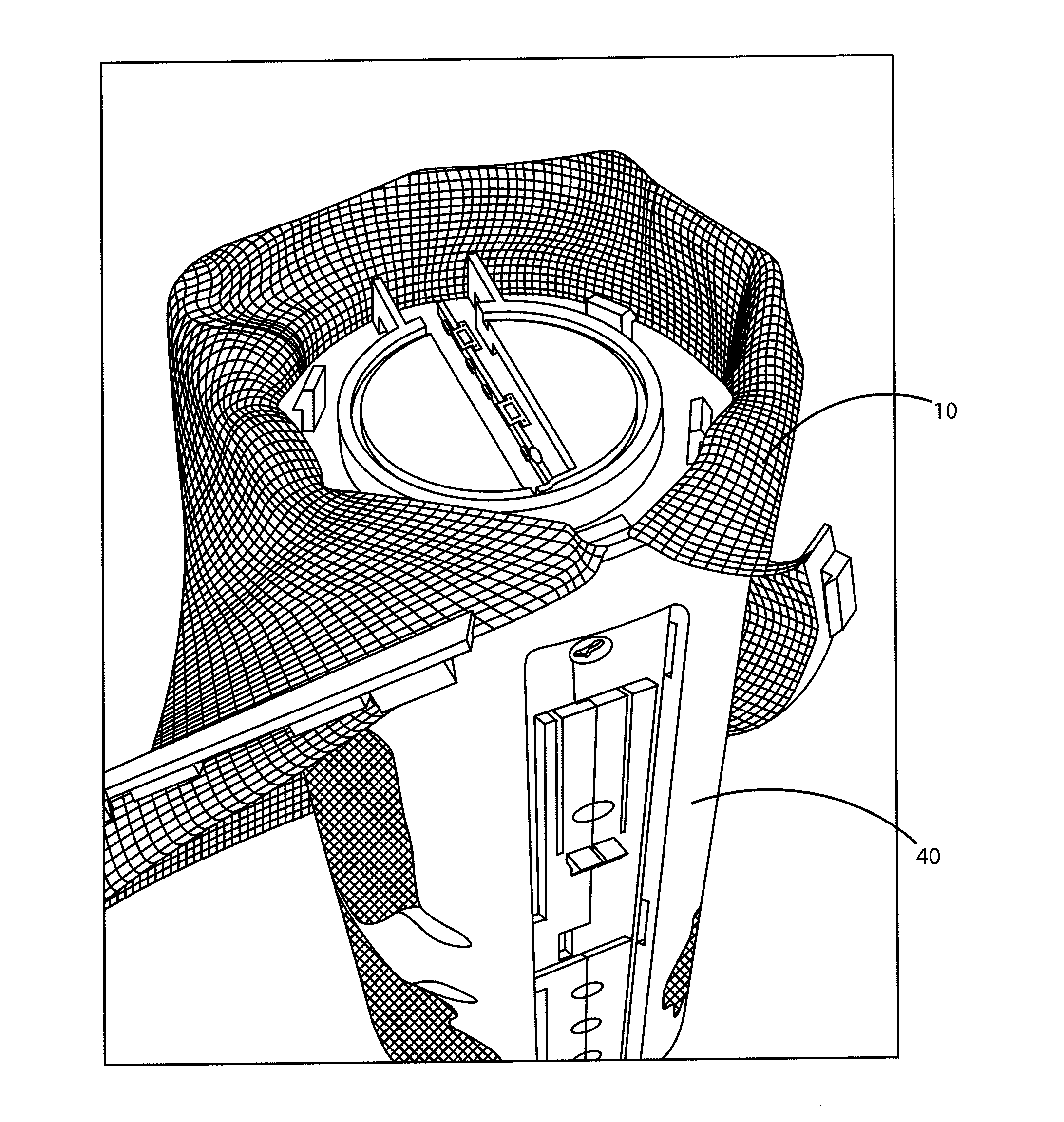
[0014]Embodiments of the invention provide a covered housing that allows fabric to be wrapped around a speaker housing in a way to reach the desired tension. A speaker fabric assembly contains frame strips bonded to the fabric that may be tucked under shoulders of a speaker housing. Once the fabric strips are secured under the shoulders, the fabric is held in tension thereby holding the fabric in the intended position and shape.

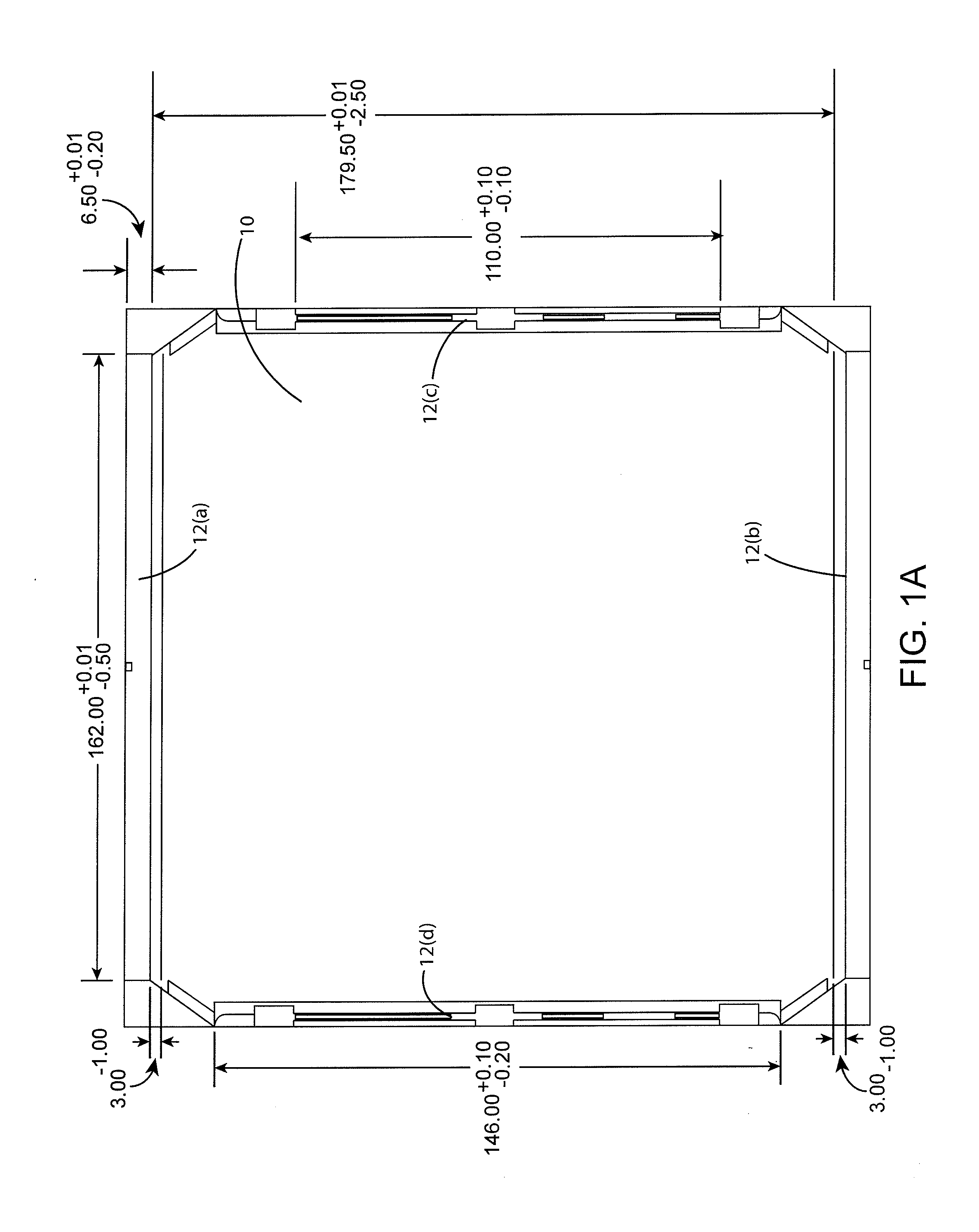
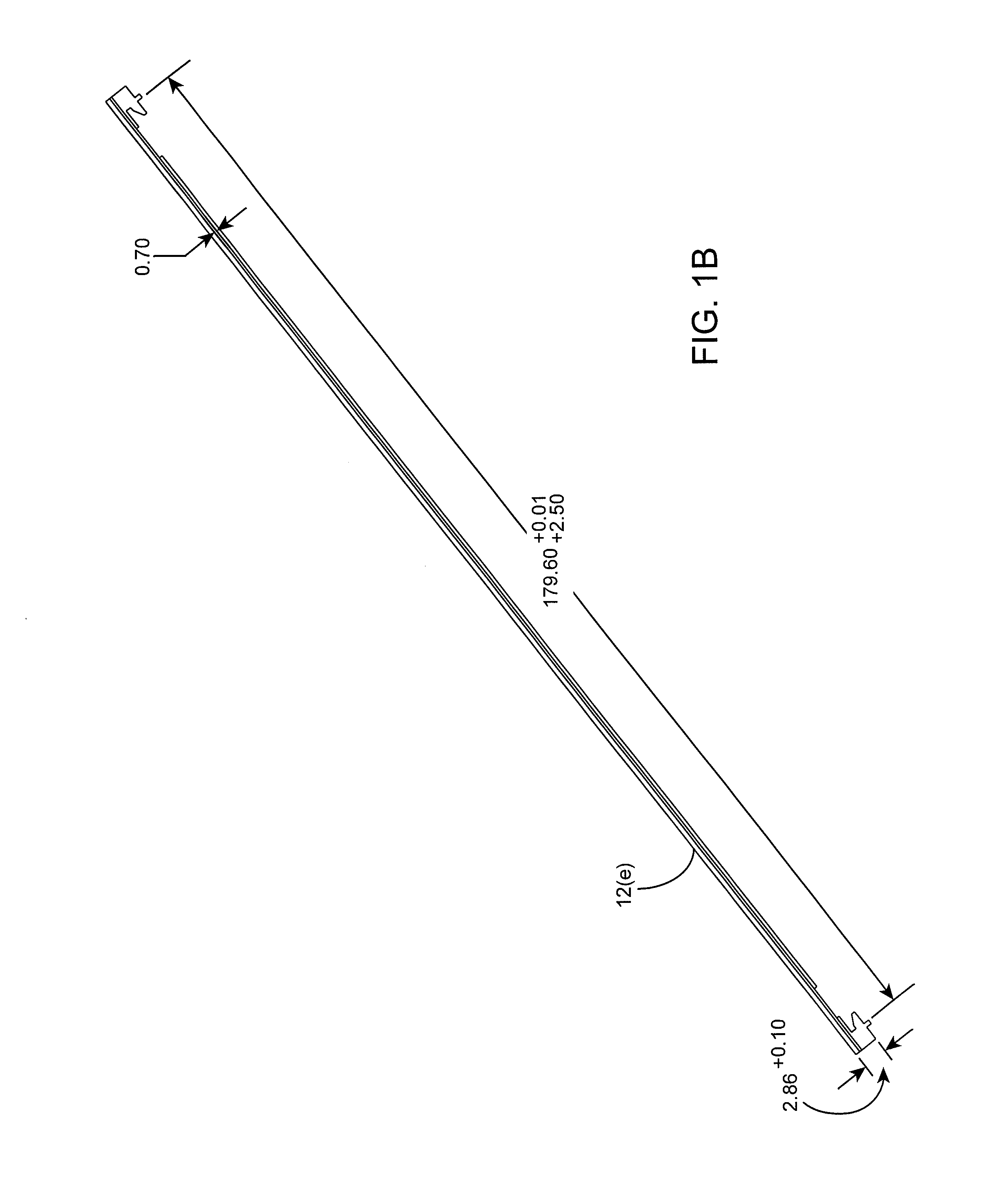
[0015]FIG. 1A shows a flat version drawing of a fabric subassembly according to an embodiment of the invention. The dimensions shown are for exemplary purposes, it is understood that embodiments of the invention can have different dimensions (e.g., longer or shorter dimensions, etc.). Likewise, for exemplary purposes a rectangular shape is shown, it is understood that different shapes may be used depending on the shape desired for the final product (e.g., triangular shape, square shape, etc.). A fabric portion 10 is shown with a frame strip 12(a)-12(d) adhere...


PUM

PropertyMeasurementUnit
widthaaaaaaaaaa
tensionaaaaaaaaaa
acoustically transparentaaaaaaaaaa

Abstract

One embodiment of the invention is directed to a process for assembly of a covered housing comprising placing a first frame strip coupled with a fabric portion, under a shoulder on a first end of a housing, pulling the fabric portion toward a second end of a housing, placing a second frame strip coupled with the fabric portion, under a shoulder on the second end of the housing, placing a third frame strip coupled with the fabric portion, under a first main body shoulder of the housing, and placing a fourth frame strip coupled with the fabric portion, under a second main body shoulder of the housing.

Description

BACKGROUND OF THE INVENTION[0001]There are many challenges for assembling fabric to a unique shaped housing. If using a unique speaker housing shape, such as a cylinder shape, it is difficult to create tension in the fabric both vertically and horizontally around the cylindrical shaped component after the fabric is assembled to a cylindrical shape. The tension needs to be high enough so that the fabric cannot simply be pulled off the housing. Accordingly, a traditional sock assembly where a fabric sock that is open on both ends is slipped over a rectangular or cylinder housing would not work because the tension along the length of the sock cannot be well controlled. Moreover, a traditional sock assembly generally requires a cap on each end to mechanically hold the sock in place. If the cap also includes additional features or controls (e.g., buttons, etc.) or connectors, these may be damaged or compromised when applying pressure to fit the cap onto the housing. This creates addition...

Claims


Application Information

Patent Timeline
Patent Type & Authority Applications(United States)
IPC IPC(8): H04R1/02
CPCH04R1/021H04R1/023Y10T29/49826
Inventor YIM, DAVIDMCGARRY, STEVE
Owner LOGITECH EURO SA
Learn More