
Wideband Data And Power Transmission Using Pulse Delay Modulation

a technology of pulse delay and wideband data, applied in the field of inductive links, can solve the problems of limited space and power available, unsafe temperature elevation, and provide a limited data bandwidth of approximately 300 khz

Active Publication Date: 2014-05-22
GEORGIA TECH RES CORP
View PDF1 Cites 18 Cited by
  • Summary
  • Abstract
  • Description
  • Claims
  • Application Information

AI Technical Summary

Benefits of technology

The patent describes a method and system for wirelessly transmitting data and power using pulse delay modulation (PDM) and a power carrier signal. The system includes a power transmitter coil, a power receiver coil, a data Tx coil, and a data Rx coil. The method involves generating a power carrier signal with a fundamental period and transmitting it along with a data waveform that is synchronized with the power carrier signal. The data waveform includes a series of pulses in synchronization with the power carrier signal. The system also includes a pulse delay detector that can determine the data packet based on the zero crossings of the interference signal. The technical effects of this technology include improved data transmission and power transfer with reduced interference, improved data accuracy, and improved system stability.

Problems solved by technology

Some of the challenges involved in designing transcutaneous data and power transmission links relate to the extremely limited space and power available to the IMD for establishing a wideband and robust connection.
However, because of the electro-magnetic field absorption in the tissue, which increases at a rate of carrier frequency squared, f2, the competing goals of low carrier frequency and high data rate often rule-out a majority of established wideband wireless protocols, such as Bluetooth or WiFi, which operate at 2.4 GHz.
Certain dedicated medical communication frequency bands exist, such as the Medical Implant Communication Service (MICS), operating in the 402˜405 MHz range, but typically can only provide a limited data bandwidth of approximately 300 kHz.
In high-performance IMDs that require wider bandwidth, however, a separate power carrier from the data carrier is typically preferred because increasing the frequency of the high amplitude power carrier can lead to unsafe temperature elevation due to excessive power loss in the tissue.
A major challenge in dual-function (power & data) inductive link designs is the cross-coupling between the two pairs of power and data coils.
Part of the challenge is that to conserve space, the coils in the IMD need to be miniaturized and co-located inside the IMD.
However, a strong power carrier signal can interfere with and / or dwarf the weak data signal on the receiver (Rx) side and make data recovery quite difficult, if not impossible.
While certain innovative coil designs can help with reducing cross-coupling, it may still be necessary to electronically filter out the power carrier interference at the receiver (Rx) input at the cost of adding to the power consumption and complexity of the IMD.
Moreover, achieving high data rates via traditional modulation schemes often requires power consuming frequency-stabilization RF circuits, such as phase-locked loops (PLL), which can add to the size, complexity and power requirements of the IMD.

Method used


Image

  • Wideband Data And Power Transmission Using Pulse Delay Modulation
  • Wideband Data And Power Transmission Using Pulse Delay Modulation
  • Wideband Data And Power Transmission Using Pulse Delay Modulation

Examples


Embodiment Construction

[0039]Some implementations of the disclosed technology will be described more fully hereinafter with reference to the accompanying drawings. This disclosed technology may, however, be embodied in many different forms and should not be construed as limited to the implementations set forth herein.

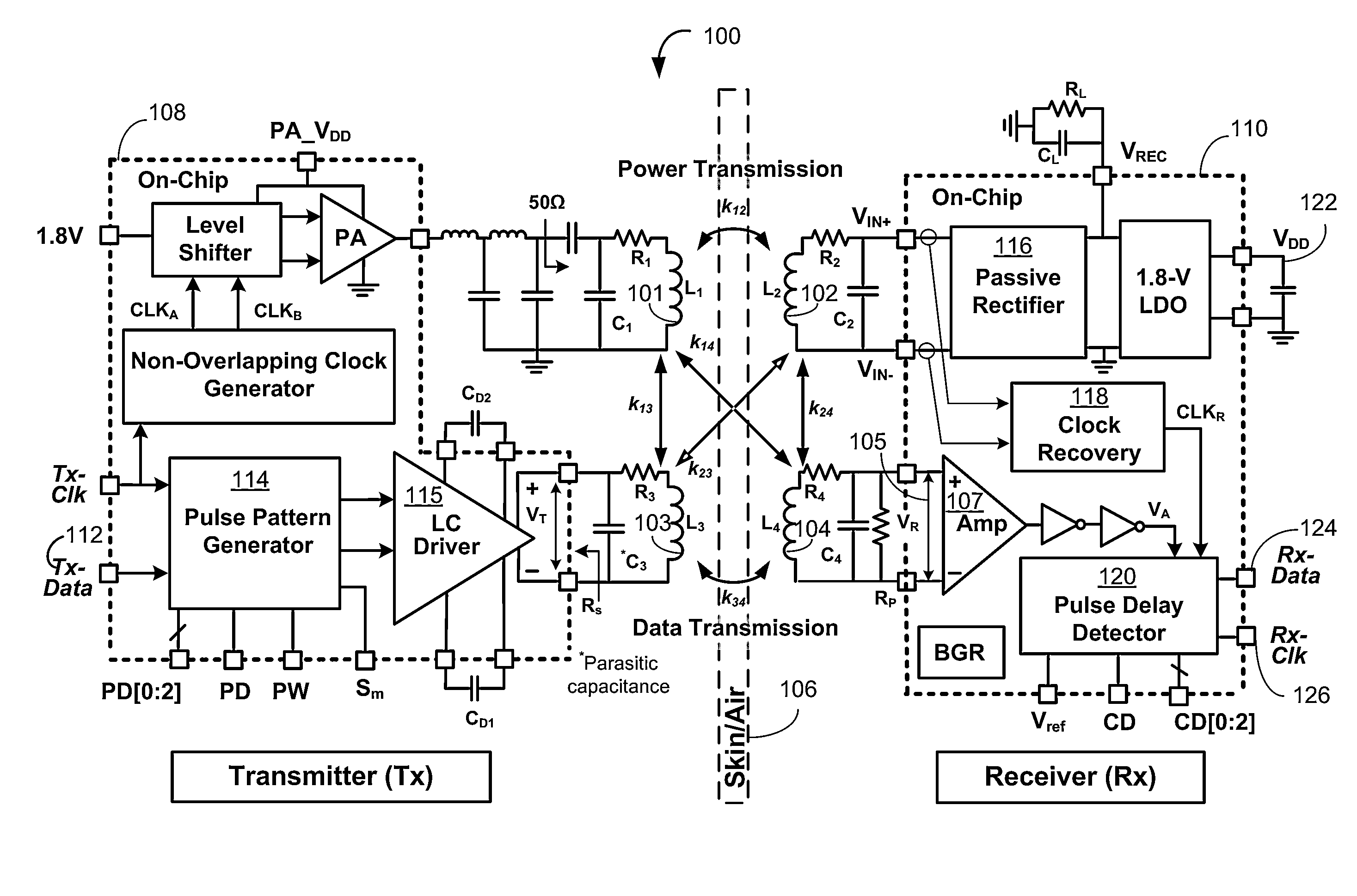
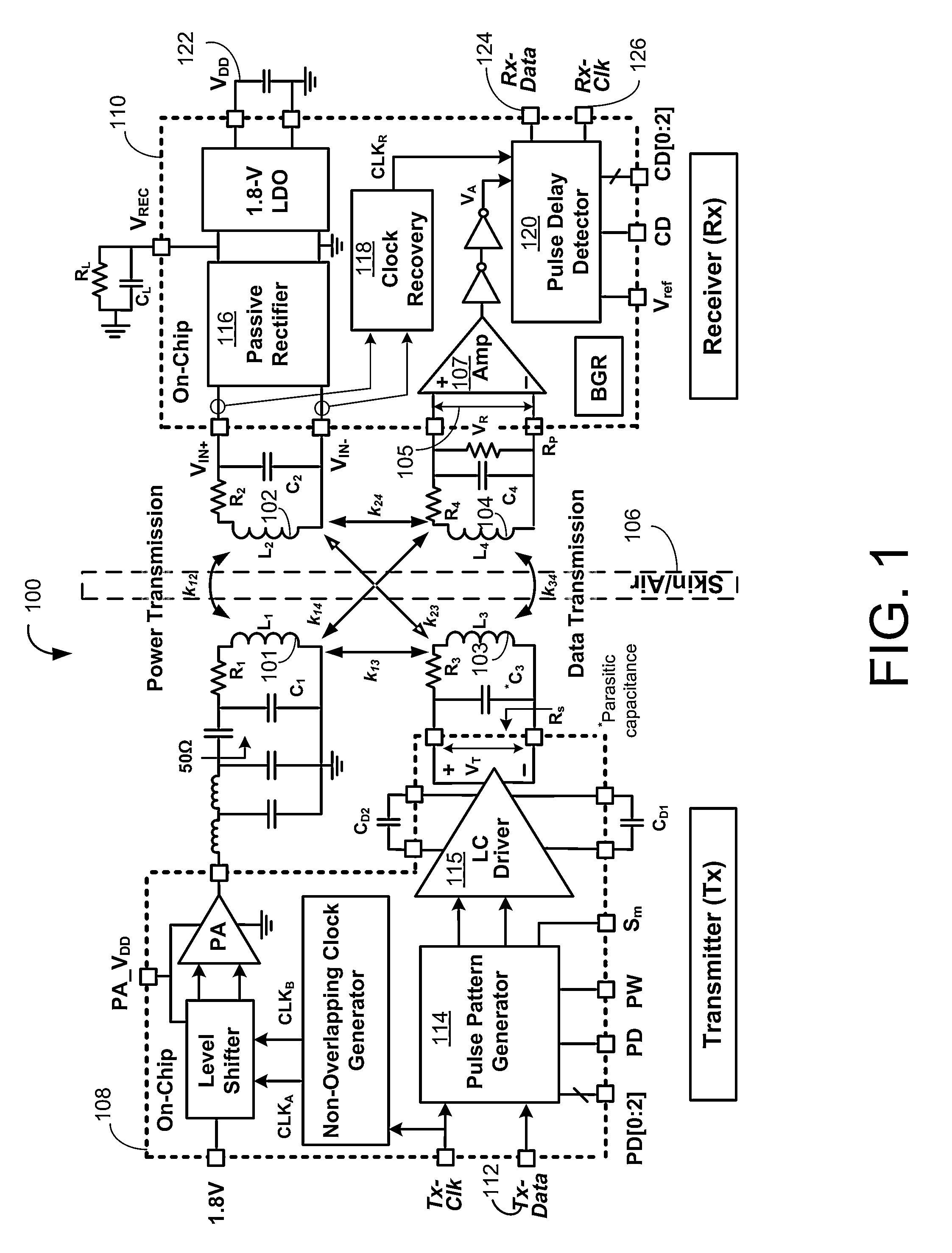
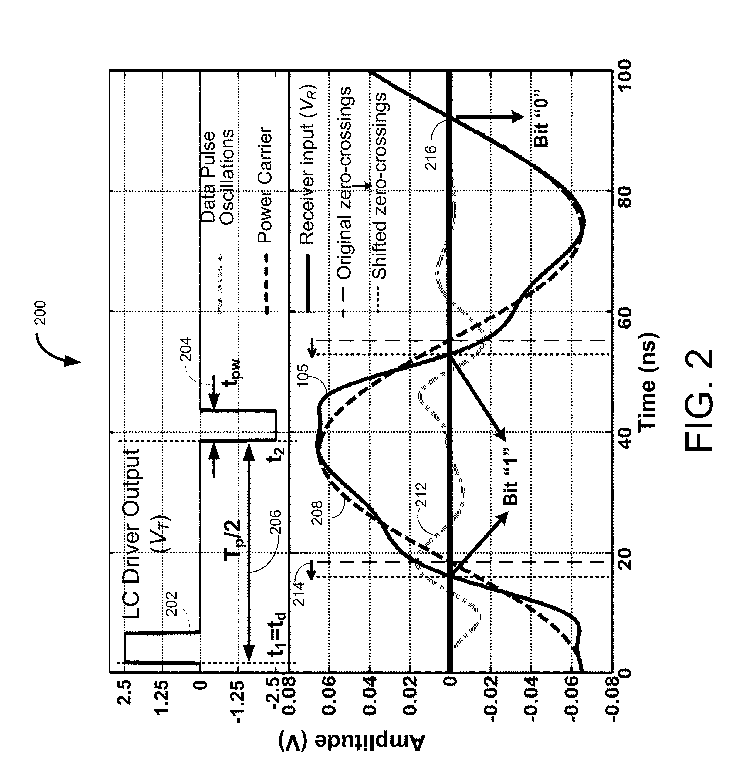
[0040]Example implementations of the disclosed technology include systems, methods, and apparatus for wirelessly transmitting data and power across inductive links of a wireless transceiver (Tx-Rx) system using Pulse Delay Modulation (PDM) for near-field simultaneous data and power transmission. According to various example implementations disclosed herein, the unavoidable (and typically unwanted) crosstalk between power and data transmission is utilized to recover the data signal at the receiver (Rx). For example, and according various implementations, power and data transmission signals may be used to drive respective transmitter (Tx) coils at the transmitter side of the wireless transceive...


PUM


Abstract

Certain implementations may include systems, methods, and apparatus for wirelessly transmitting data and power across inductive links using pulse delay modulation (PDM). According to an example implementation, a method is provided that includes generating a power carrier signal; generating a data waveform from a series of binary bits, the data waveform including a series of pulses in synchronization with the power carrier signal; transmitting, from one or more transmitting (Tx) coils of an inductive link, the power carrier signal and the data waveform; receiving, by one or more receiving (Rx) coils of the inductive link, an interference signal, the interference signal based at least in part on a superposition of the transmitted power carrier signal and the transmitted data waveform; determining zero crossings of the received interference signal; determining delays associated with the zero crossings; and determining the data packet based at least in part on the delays.

Description

RELATED APPLICATIONS[0001]This application is related to provisional application Ser. No. 61 / 728,259, filed on 20 Nov. 2012, entitled: “Wideband Data and Power Transmission Using Pulse Delay Modulation,” the contents of which are hereby incorporated by reference in their entirety.STATEMENT REGARDING FEDERALLY SPONSORED RESEARCH OR DEVELOPMENT[0002]This invention was made with Government support under the following grants: Grant Number ECCS-824199, awarded by the National Science Foundation; Grant Number 1R01NS062031, awarded by the National Institute of Neurological Diseases and Stroke (NINDS); and Grant Number 5R21EB009437, awarded by the National Institute of Biomedical Imaging and Bioengineering (NIBIB) at the National Institutes of Health. The Government has certain rights in the invention.RELATED LITERATURE[0003]This application is also related to the conference publication entitled: “Pulse Delay Modulation (PDM) A New Wideband Data Transmission Method to Implantable Medical De...

Claims


Application Information

Patent Timeline
Patent Type & Authority Applications(United States)
IPC IPC(8): H04W52/02
CPCH04W52/0209Y02D30/70
Inventor GHOVANLOO, MAYSAMKIANI, MEHDI
Owner GEORGIA TECH RES CORP
Learn More