Detecting device and method for liquid crystal panel

a detection device and liquid crystal panel technology, applied in measurement devices, electrical testing, instruments, etc., can solve the problems of weakening the detection reducing the circuit area weakening so as to improve the detecting ability of the liquid crystal panel and sharpen the competitive edge of products.

Inactive Publication Date: 2014-05-22
TCL CHINA STAR OPTOELECTRONICS TECH CO LTD
View PDF3 Cites 4 Cited by
  • Summary
  • Abstract
  • Description
  • Claims
  • Application Information

AI Technical Summary

Benefits of technology

The present invention is a detecting device for liquid crystal panels that improves the ability to detect and measures the competitive edge of products with liquid crystal panels. The device has lines and connecting ports for detecting signals, which convert the way of detecting the lighting of the liquid crystal panel. Additionally, after use, the detecting device can be easily detached for recycling, which further improves the ability to detect and reduces the area of the circuit on the liquid crystal panel.

Problems solved by technology

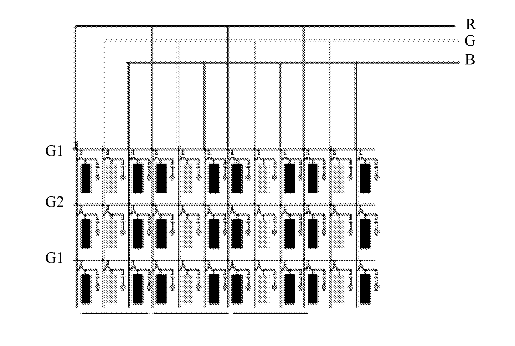
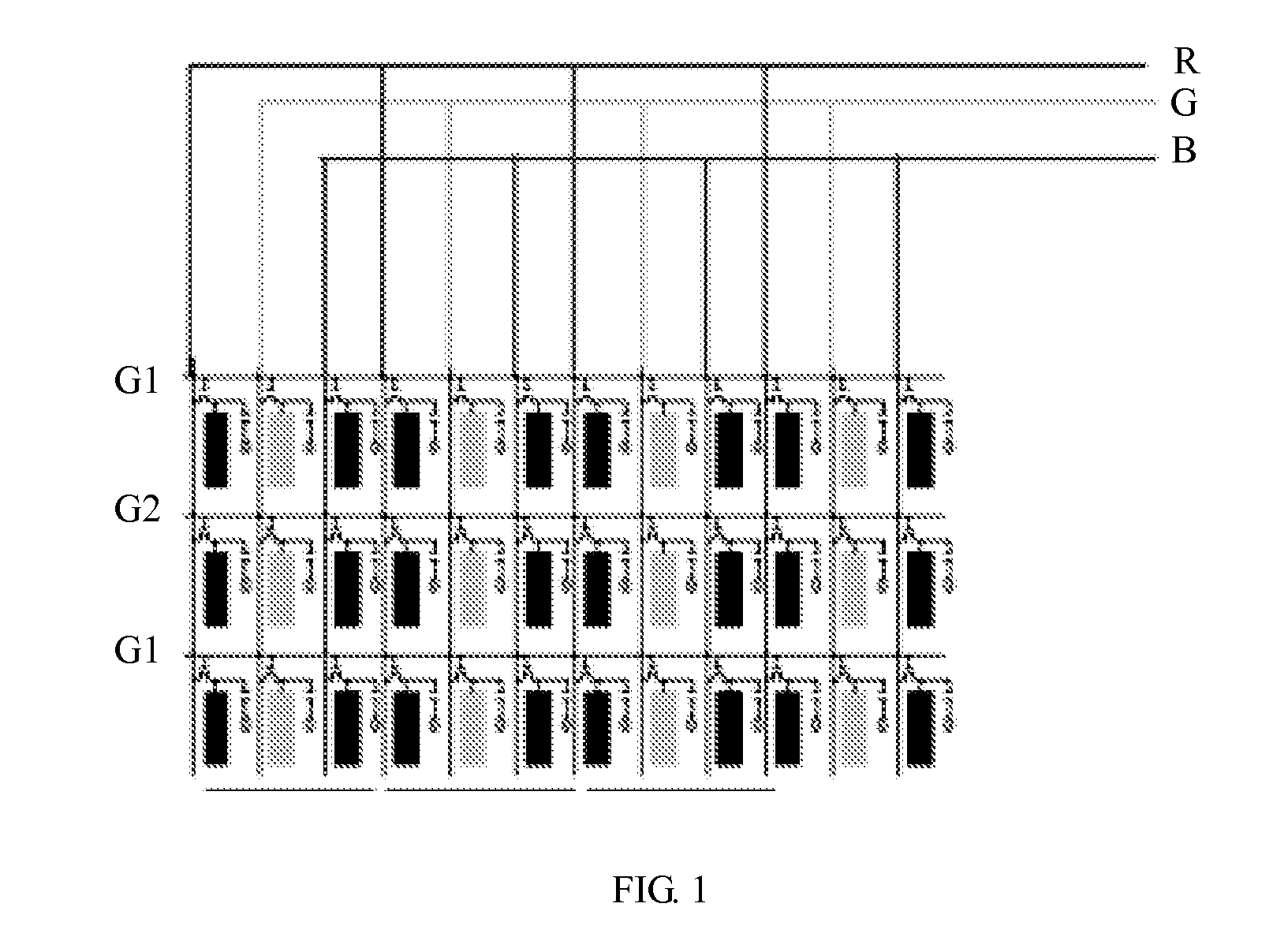
However, detecting the TFT-LCD in the 2D1G and 3D2G ways may cause two adjacent data lines to have same polarities, which weakens the detecting ability of the liquid crystal panel.
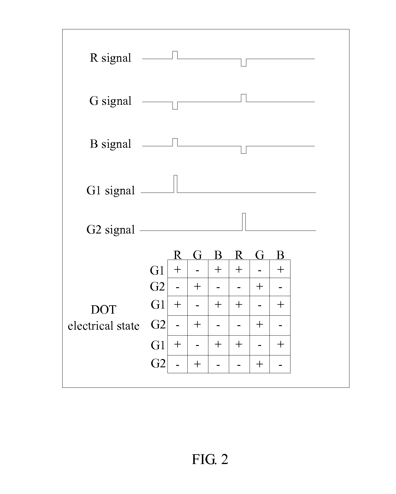
According to the obtained DOT electrical state, the DOT receiving the R signal and the B signal for detection has the same electrical property, which weakens the detecting ability of the liquid crystal panel.
Additionally, after the lighting detection of the liquid crystal panel is finished, the detecting device is detached to be recycled, which not only improves the detecting ability of the liquid crystal panel but also reduces the area of the circuit on the liquid crystal panel and further sharpens the competitive edge of the liquid crystal panel.

Method used


Image

  • Detecting device and method for liquid crystal panel
  • Detecting device and method for liquid crystal panel
  • Detecting device and method for liquid crystal panel

Examples


Embodiment Construction

[0038]The disclosure is illustrated by way of example and not by way of limitation in the figures of the accompanying drawings in which like references indicate similar elements. It should be noted that references to “an” or “one” embodiment is this disclosure are not necessarily to the same embodiment, and such references mean at least one.

[0039]Referring to FIG. 3, a detecting device for detecting a liquid crystal panel in accordance with an embodiment of the present disclosure is schematically shown. The detecting device includes a first detecting unit 1 connected to data lines of a to-be-detected liquid crystal panel 100, a second detecting unit 2 connected to scanning lines of the liquid crystal panel 100, and a signal generator 3 connected to the first detecting unit 1 and the second detecting unit 2. Both the first detecting unit 1 and the second detecting unit 2 include a line area 10 and a number of connecting ports 20 which are arranged on one side of the line area 10 and ...


PUM


Abstract

A detecting device for detecting a liquid crystal panel is provided. The detecting device includes a first detecting unit connected to data lines on the liquid crystal panel, a second detecting unit connected to scanning lines on the liquid crystal panel, and a signal generator connected to the first detecting unit and the second detecting unit; both the first detecting unit and the second detecting unit comprise a line area and connecting ports arranged on one side of the line area and connected to the signal generator; a plurality of lines are arranged on the line area, the lines having the same properties are connected together with one ends thereof respectively connected to the connecting ports and the other ends thereof connected to the corresponding signal lines arranged on the liquid crystal panel.

Description

BACKGROUND[0001]1. Technical Field[0002]The present disclosure relates to liquid crystal displaying technologies and, particularly, to a detecting device and a detecting method used for detecting a liquid crystal.[0003]2. Description of Related Art[0004]With the development of electronic technology, flat displays such as liquid crystal displays, plasma displays, and OLED displays (Organic Light-Emitting Diode) have gained rapid development. Among the flat displays, liquid crystal displays are thin, small and energy-efficient, making liquid crystal displays gradually replace code cathode displays.[0005]TFT-LCD is a type of flat displays commonly used. Generally, the lighting detection way of the TFT-LCD includes 2D1G (units formed by two data lines and one gate line) and 3D2G (units formed by three data lines and two gate lines). However, detecting the TFT-LCD in the 2D1G and 3D2G ways may cause two adjacent data lines to have same polarities, which weakens the detecting ability of t...

Claims


Application Information

Patent Timeline
Patent Type & Authority Applications(United States)
IPC IPC(8): G09G3/00
CPCG09G3/006G09G3/3648
Inventor HUANG, HAOLIU, CHUNPAN, CHANG-HUNG
Owner TCL CHINA STAR OPTOELECTRONICS TECH CO LTD
Why Eureka
Try Eureka