
Baseball Bat

a bat and ball technology, applied in the field of baseball bats, can solve the problems of reducing the life of the bat, dents or dings on the bat, and the bat outperforms the traditional wooden bat, so as to improve the rebound effect and dampen the vibration, the effect of easy manufacturing

Active Publication Date: 2014-05-15
PEGNATORI CARL
View PDF5 Cites 7 Cited by
  • Summary
  • Abstract
  • Description
  • Claims
  • Application Information

AI Technical Summary

Benefits of technology

The present invention provides a bat with walls that are not secured with each other, which allows each wall to flex independently of any adjacent wall. This enhances the rebound effect and damping vibrations. The bat has a multiwall design that is easy to manufacture. The insert of the bat frame absorbs a greater amount of energy than inserts of prior art bats that are physically attached to the bat frame, resulting in a higher performance bat with a larger rebound effect. The insert also damps vibrations by not being connected to the frame of the bat.

Problems solved by technology

It was found that these bats outperformed traditional wooden bats because of a “rebound” effect present in aluminum / composite bats.
However thinner walls also decreased the life of the bat as the wall would fatigue and no longer return to its original position; leaving dents or dings on the bat.
However this simplicity comes at a cost to performance as less energy is absorbed from the ball's impact with the bat resulting in a less than desired rebound effect.
Although the bat will always vibrate the amount of vibrations may sometimes be felt by the batter and can lead to the batter experiencing a “stinging” sensation in their hands.
First it can be easily seen that vibration energy directly subtracts from flexing energy in that the more energy absorbed by vibration the less energy is available to be absorbed for flexing.
Vibrations also adversely impact the rebound effect by actively working against the wall flexing.
As the wall is flexed energy will have to be expended to overcome the vibrations resulting in a reduction of the energy used to flex the wall and therefore a less than optimal rebound effect.

Method used


Image

  • Baseball Bat
  • Baseball Bat
  • Baseball Bat

Examples


Embodiment Construction

[0030]While preferred embodiments of the present invention have been shown and described herein, it will be obvious to those skilled in the art that such embodiments are provided by way of example only. Numerous variations, changes, and substitutions will now occur to those skilled in the art without departing from the invention. It should be understood that various alternatives to the embodiments of the invention described herein may be employed in practicing the invention.

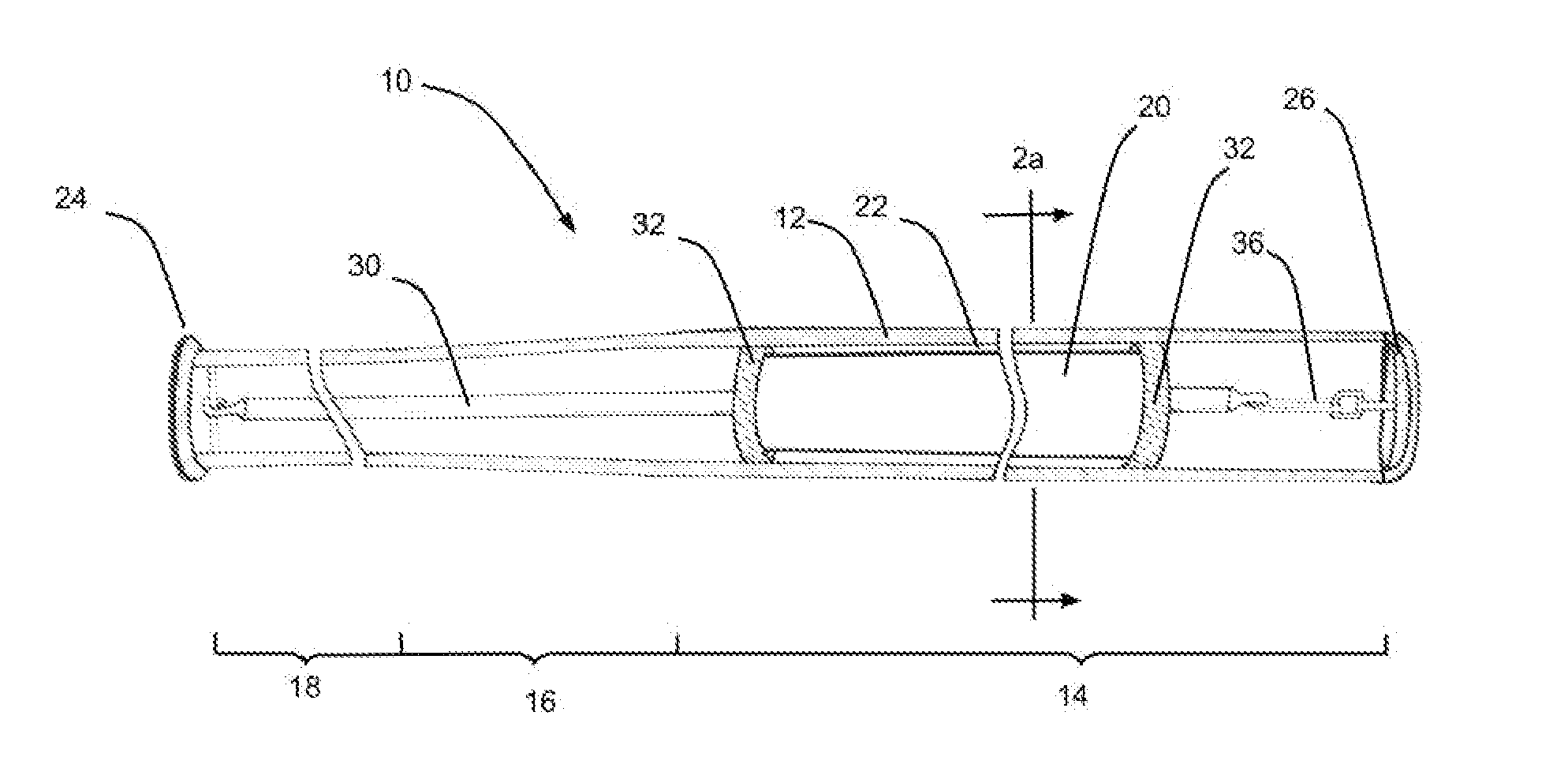
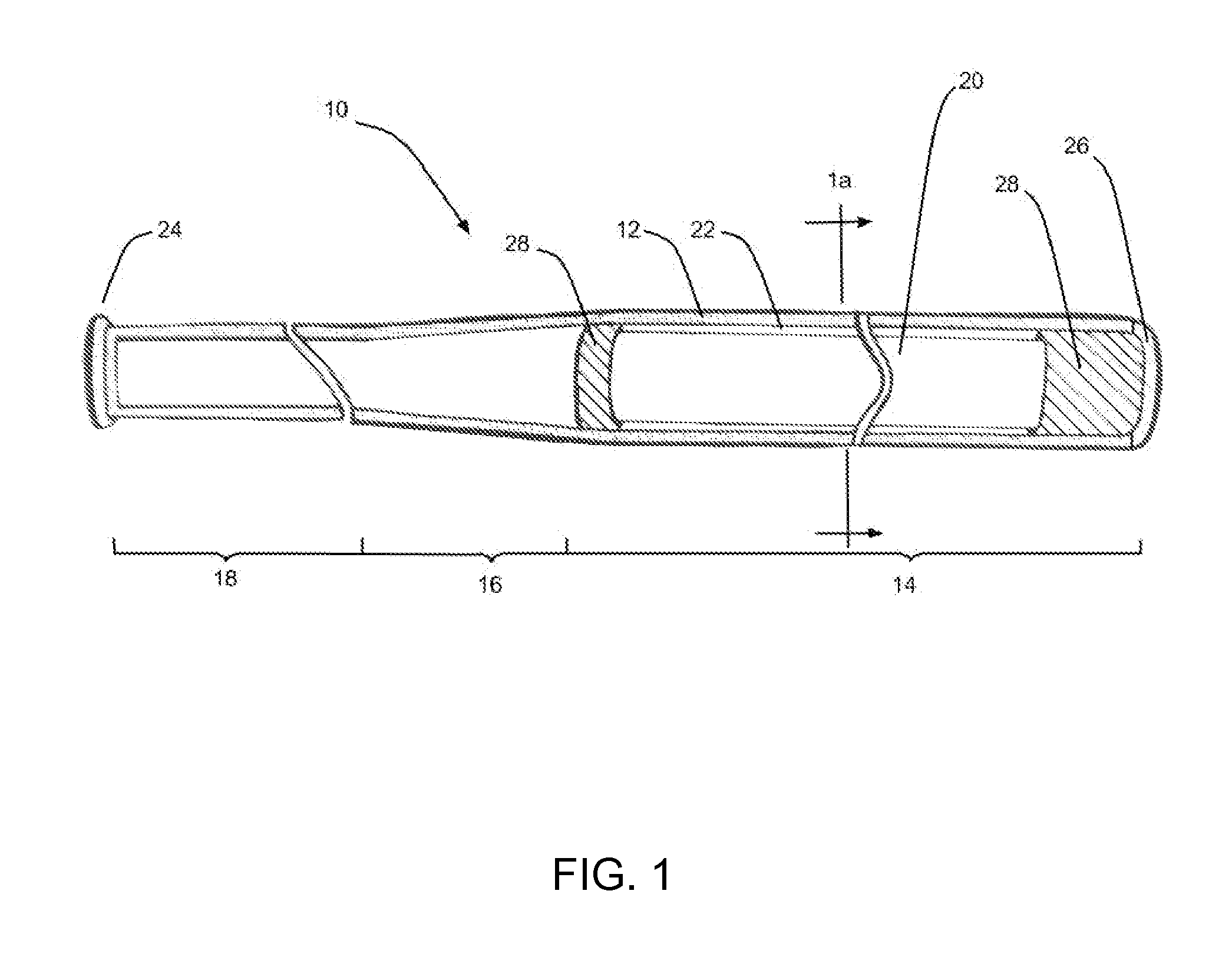
[0031]Referring to FIG. 1, a bat 10 has a tubular aluminum frame 12 with a relatively large-diameter hitting portion 14, an intermediate tapering portion 16, and a relatively small-diameter handle portion 18.

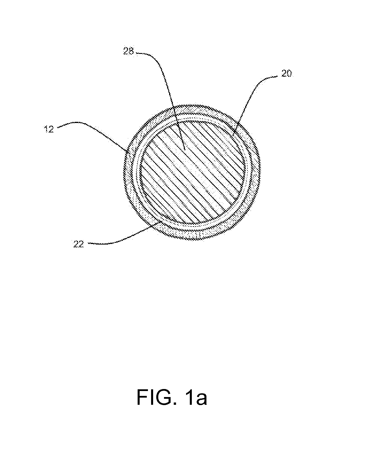
[0032]To provide for an improved rebound effect to better transfer of energy from the bat to a ball, the present invention provides for a tubular insert 20 to be suspended within the hitting portion 14 of the frame 12. The insert 20 has an outer diameter less than the inner diameter of hitting portion 14. As ...


PUM


Abstract

A hollow non-wood baseball or softball bat wherein the impact portion of the bat contains an inner barrel that is positioned by means of a (i) foam insert, (ii) tube extending from the bat's knob, or (iii) line attached to the bat's knob and end cap and extending throughout the bat such that the inner barrel does not come into contact with the inside wall of the bat when the bat is at rest yet when swung the inner barrel is allowed to move so as to amplify the rebound effect given to the ball upon impact with the bat.

Description

CROSS-REFERENCE TO RELATED APPLICATIONS[0001]This application claims the benefit of U.S. Provisional Application No. 61 / 677,076, filed Jul. 30, 2012, which is incorporated herein by reference in its entirety.[0002]In addition this application references the following US patents:[0003]U.S. Pat. No. 5,415,398 filed Jun. 1994 by Eggiman.[0004]U.S. Pat. No. 5,511,777 filed Feb. 1994 by McNeely.[0005]U.S. Pat. No. 6,425,836 filed Dec. 1999 by Misono et al.[0006]U.S. Pat. No. 8,100,787 filed Jan. 2010 by Smith.BACKGROUND OF THE INVENTION[0007]1. Field of the Invention[0008]The present invention is generally related to the field of baseball and softball and more specifically to a baseball or softball bat.[0009]2. Description of the Related Art[0010]High performance baseball and softball bats, hereinafter referred to simply as “baseball bats” or “bats”, are primarily made from aluminum alloys, composite materials, or some combination thereof. These bats are tubular (hollow inside) so as to ...

Claims


Application Information

Patent Timeline
Patent Type & Authority Applications(United States)
IPC IPC(8): A63B59/00A63B59/06
CPCA63B59/06A63B59/0092A63B2209/00A63B60/16A63B60/54A63B2102/18A63B59/50A63B60/04A63B2102/182A63B59/54A63B60/46A63B60/00
Inventor PEGNATORI, CARL
Owner PEGNATORI CARL
Learn More