
Illuminating Device Having Folding Solar Panels

a solar panel and illumination device technology, applied in outdoor lighting, lighting and heating equipment with built-in power, etc., can solve the problems of affecting the power generation efficiency of the device, prone to damage, and occupying a lot of space, and achieve the effect of easy folding and compromising the electric circuit board and battery

Active Publication Date: 2014-05-15
CHANG KUEI HSIANG
View PDF11 Cites 10 Cited by
  • Summary
  • Abstract
  • Description
  • Claims
  • Application Information

AI Technical Summary

Benefits of technology

The present invention is an illuminating device with folding solar panels mounted inside the lamp cover. The device has a retaining sheet with elastic supporting brackets that secure the light source and folding holder inside the lamp cover. A water-resistant gasket is used to tightly secure the lead line, anode wire, and cathode wire together, preventing water from leaking through. The folding holder has a base plate and two U-shaped side walls that can fold easily. The technical effects of the invention include reducing the size of the opening of the lamp cover to allow the same solar panel to pass through, while maintaining the working efficiency of the solar panel, and an esthetic appearance and flexible construction.

Problems solved by technology

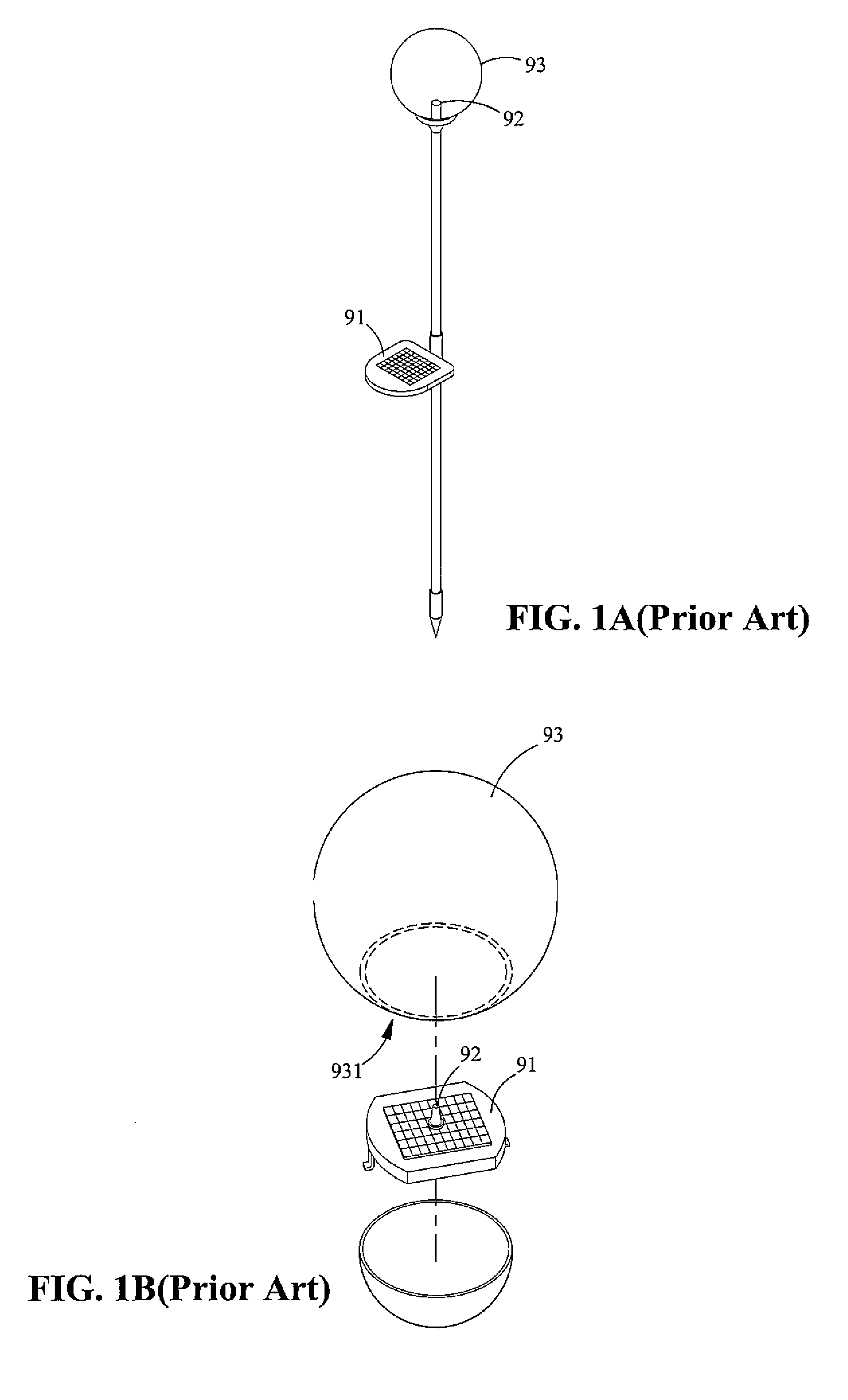
However, such an arrangement occupies a lot of space and is unesthetic.
Further, as the solar panel 91 is exposed to outside the lamp cover, it is prone to be damaged by weather or inappropriate operation of user.
Besides, as the solar panel 91 is located at a lower altitude, it tends to be blocked by the surrounding plants or objects, and the power generating efficiency thereof is seriously affected.
Accordingly, the volume of the illuminating device will be increased, and the base device mounted at the opening becomes bulky, giving an unaesthetic appearance to the lamp, which is disadvantageous to the gardening or decoration arrangement.

Method used


Image

  • Illuminating Device Having Folding Solar Panels
  • Illuminating Device Having Folding Solar Panels
  • Illuminating Device Having Folding Solar Panels

Examples


Embodiment Construction

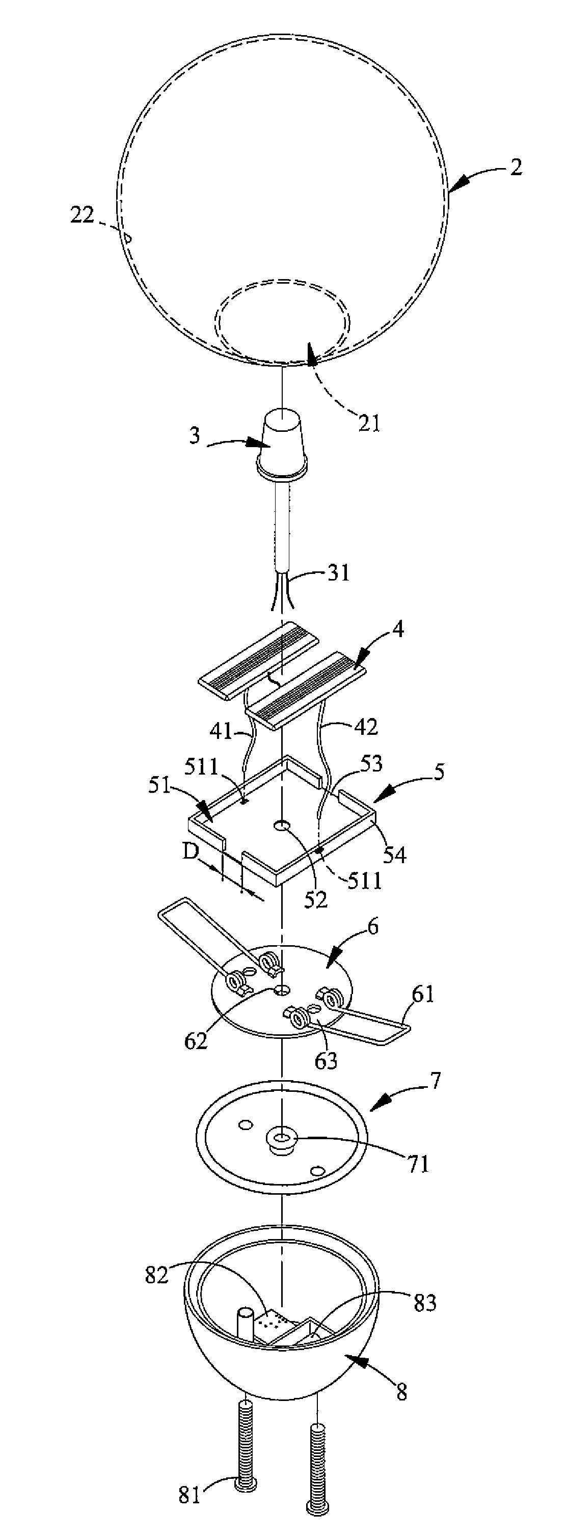
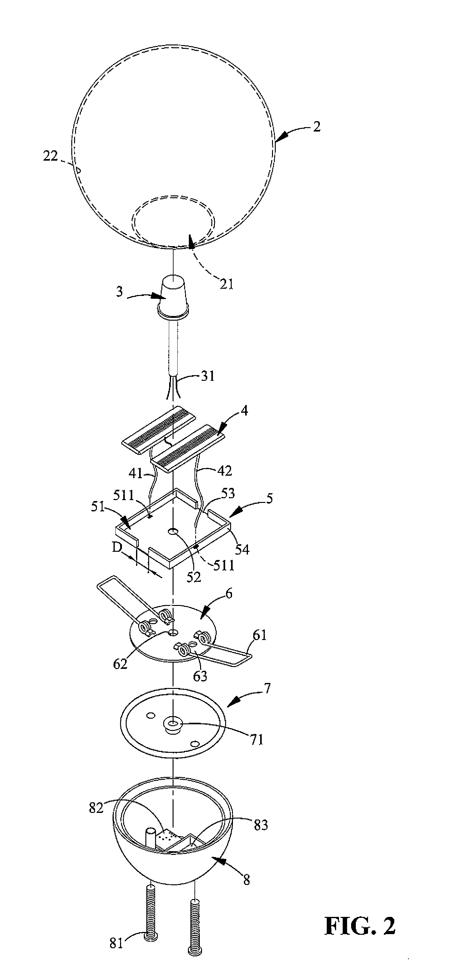
[0019]In describing the preferred embodiment of the present invention, reference will be made to FIGS. 2 and 3, in which FIG. 2 is an exploded view of a preferred embodiment according to the present invention, and FIG. 3 is a sectional view of the preferred embodiment according to the present invention. As shown in the figures, an illuminating device having folding solar panels according to the present invention comprises a lamp cover 2, a light source 3, a pair of solar panels 4, a folding holder 5, a retaining sheet 6, a water-resistant gasket 7, a lower housing 8, an electric circuit board 82, and a battery 83.

[0020]The lamp cover 2 includes an opening 21, which is smaller than the deployed area of the folding holder 5. That is, when the folding holder 5 is extended, or when it is in its unfold form, it may not pass through the opening 21. The light source 3 is electrically connected to the lead line 31, and the pair of solar panels 4 is electrically connected to the light source...


PUM


Abstract

An illuminating device having folding solar panels, which comprises a lamp cover, a light source, two solar panels, and a folding holder on which the two solar panels are positioned. The opening of the lamp cover is smaller than the deployed area of the folding holder. When it is intended to place the light source, solar panels, and folding holder inside the lamp cover, the folding holder are folded by a predetermined angle so as to pass through the opening of the lamp cover. Accordingly, the illuminating device may significantly reduce the overall volume thereof without compromising the working efficiency. The illuminating device is flexible in arrangement and assembly, and is also more flexible in construction since the solar panels may be positioned at the highest portion to absorb more sunlight.

Description

TECHNICAL FIELD[0001]The present invention is related to an illuminating device having folding solar panels mounted inside a lamp cover and, more specifically, an illuminating device that does not need an external power supply, but operates to store electricity and illuminate by means of electricity generated by solar energy.BACKGROUND OF THE INVENTION[0002]One common illuminating device that uses solar energy for gardening or decoration purpose is as shown in FIG. 1A. Such an illuminating device has a solar panel 91 provided outside a lamp cover 93. However, such an arrangement occupies a lot of space and is unesthetic. Further, as the solar panel 91 is exposed to outside the lamp cover, it is prone to be damaged by weather or inappropriate operation of user. Besides, as the solar panel 91 is located at a lower altitude, it tends to be blocked by the surrounding plants or objects, and the power generating efficiency thereof is seriously affected.[0003]To overcome the above defect, ...

Claims


Application Information

Patent Timeline
Patent Type & Authority Applications(United States)
IPC IPC(8): F21L4/00F21L4/08F21V31/00
CPCF21L4/00F21V31/005F21L4/08F21V3/00F21W2131/10F21W2131/109Y02B20/72F21S9/037F21V15/01F21V17/06F21V23/002
Inventor CHANG, KUEI-HSIANG
Owner CHANG KUEI HSIANG
Learn More