
Light source module and manufacturing method thereof

a technology of light source module and manufacturing method, which is applied in the direction of planar/plate-like light guide, lighting and heating apparatus, instruments, etc., can solve the problems of high production cost, difficult to fabricate large-sized or ultra-thin light guiding plate, high cost of back light module production, etc., and achieve the effect of improving the light coupling efficiency

Inactive Publication Date: 2014-05-08
WISTRON CORP
View PDF14 Cites 55 Cited by
  • Summary
  • Abstract
  • Description
  • Claims
  • Application Information

AI Technical Summary

Benefits of technology

The patent provides a light source module that improves the efficiency of coupling light from a light emitting unit to a light guiding plate. The module includes a light coupling unit at the light incident surface of the plate to increase the amount of light emitted. The manufacturing process involves separately producing the light guiding plate and coupling unit, simplifying the production procedure and reducing costs.

Problems solved by technology

Therefore, the costs for producing thin back light modules are high, which restrains the demand.
However, it is difficult to fabricate large-sized or ultra-thin light guiding plates with the current technology, and there are many limitations to the application thereof Hence, how to reduce the production costs and at the same time decrease the thickness of the light guiding plate has become an important issue that needs to be solved in this field.

Method used


Image

  • Light source module and manufacturing method thereof
  • Light source module and manufacturing method thereof
  • Light source module and manufacturing method thereof

Examples


Embodiment Construction

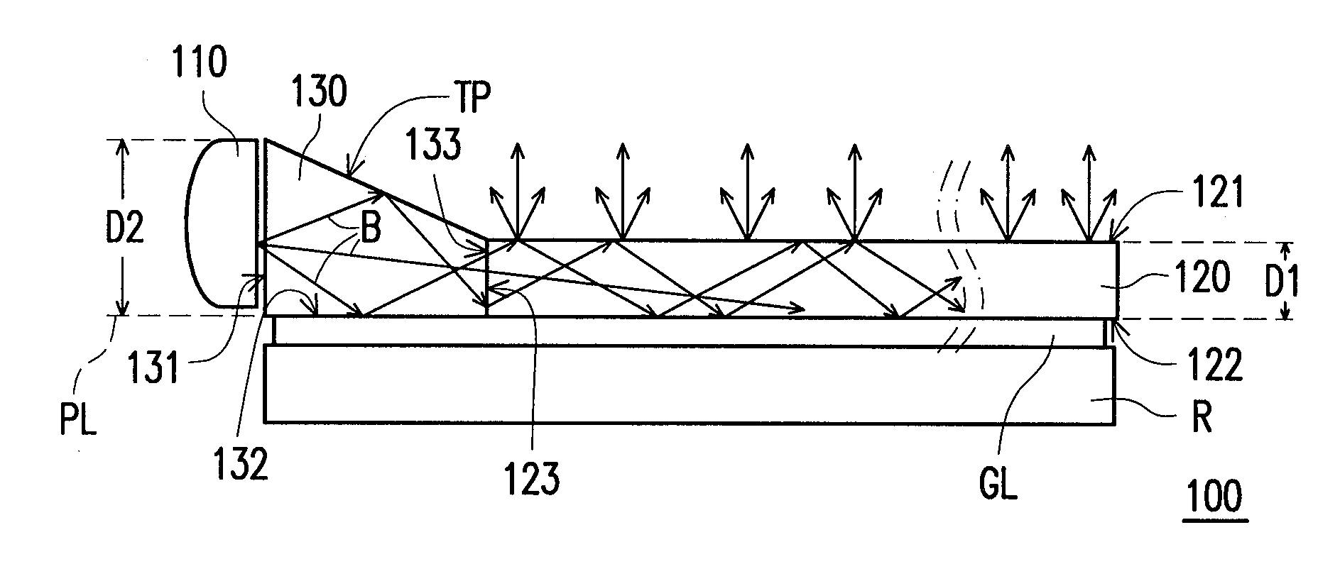
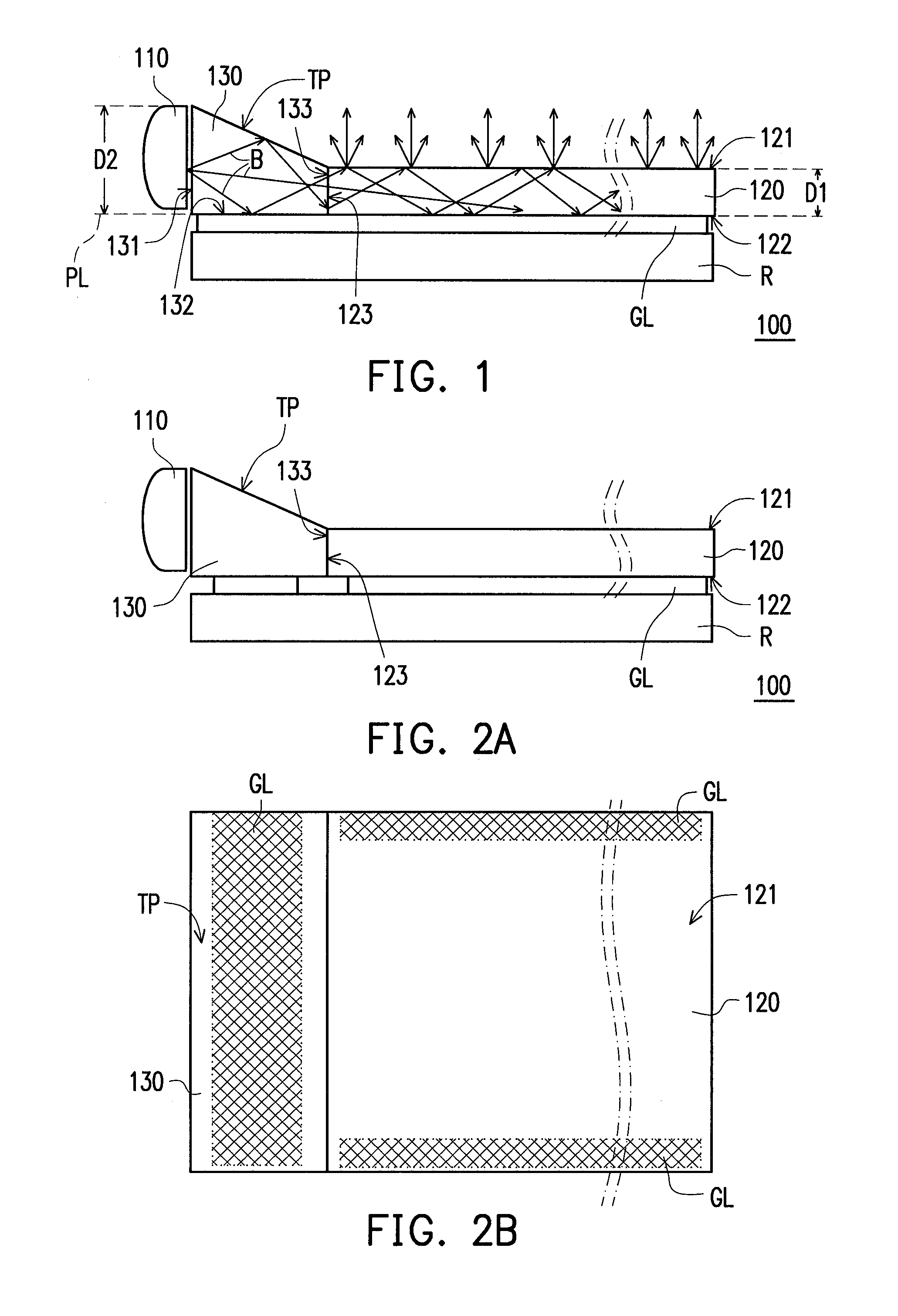
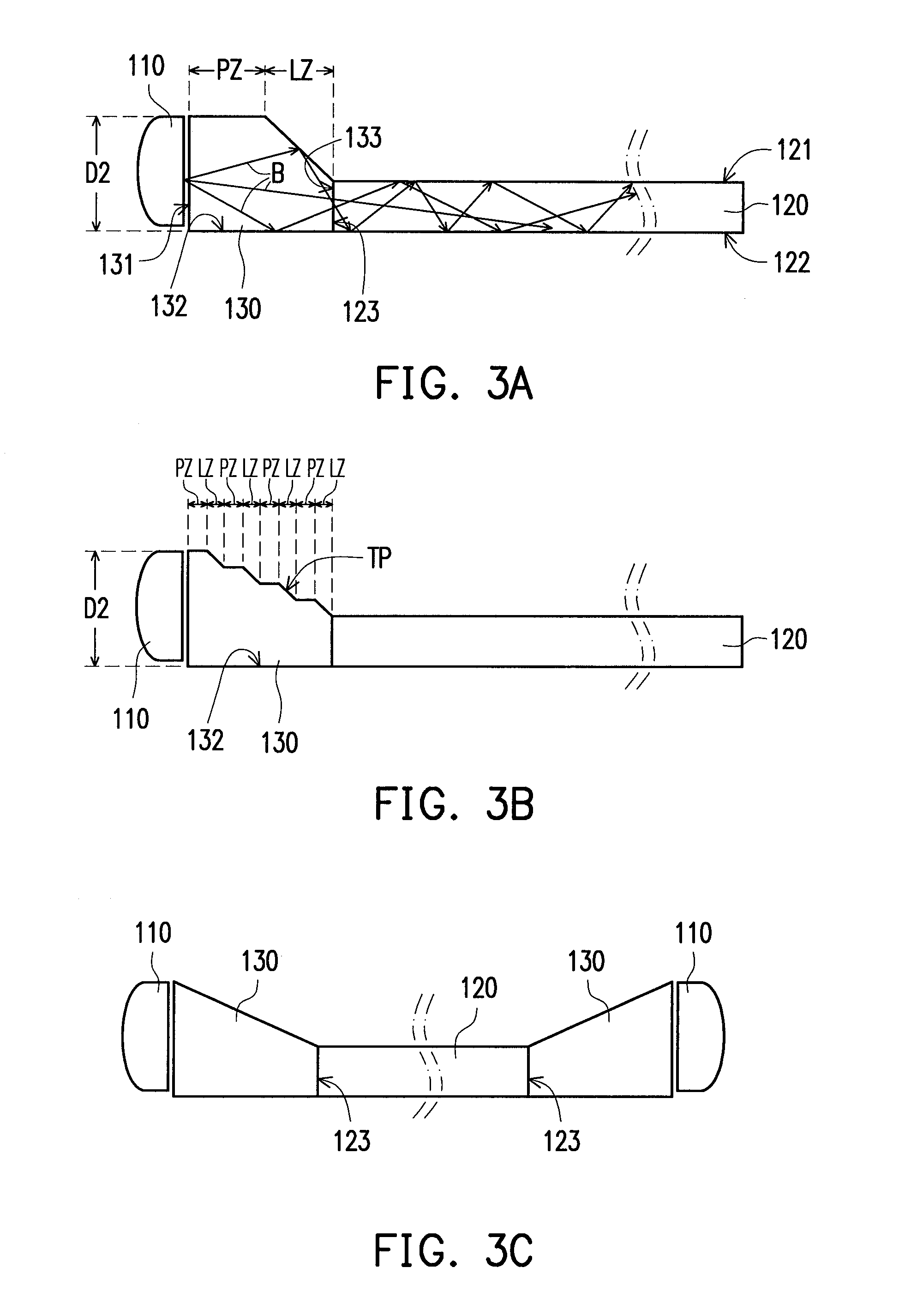
[0045]FIG. 1 is a schematic view of a light source module according to an embodiment of the disclosure. With reference to FIG. 1, in this embodiment, a light source module 100 includes at least one light emitting unit 110, a light guiding plate 120, and at least one light coupling unit 130. The light emitting unit 110 is adapted for emitting a light beam B. The light guiding plate 120 has a first light emitting surface 121, a first bottom surface 122, and at least one first light incident surface 123, wherein the first light emitting surface 121 is opposite to the first bottom surface 122, and the first light incident surface 123 connects the first light emitting surface 121 and the first bottom surface 122. The light coupling unit 130 has a second light incident surface 131 and a second light emitting surface 133. The light emitting unit 110 is disposed beside the second light incident surface 131. The light beam B enters the light coupling unit 130 through the second light inciden...


PUM

PropertyMeasurementUnit
Angleaaaaaaaaaa
Thicknessaaaaaaaaaa
Angleaaaaaaaaaa

Abstract

A light source module including a light emitting unit for emitting a light beam, a light guiding plate, and a light coupling unit is provided. The light guiding plate has a first light emitting surface, a first bottom surface, and a first light incident surface, wherein the first light emitting surface is opposite to the first bottom surface, and the first light incident surface connects the first light emitting surface and the first bottom surface. The light coupling unit has a second light incident surface and a second light emitting surface in contact with the first light incident surface. The light emitting unit is disposed beside the second light incident surface. The light beam enters the light coupling unit through the second light incident surface, exits the light coupling unit through the second light emitting surface, and then enters the light guiding plate through the first light incident surface.

Description

CROSS-REFERENCE TO RELATED APPLICATION[0001]This application claims the priority benefit of China application serial no. 201210442576.4, filed on Nov. 7, 2012. The entirety of the above-mentioned patent application is hereby incorporated by reference herein and made a part of this specification.BACKGROUND OF THE DISCLOSURE[0002]1. Field of the Disclosure[0003]The disclosure relates to a light source module and a manufacturing method thereof and more particularly relates to a light source module with a light coupling unit and a manufacturing method thereof.[0004]2. Description of Related Art[0005]The advance of display technology in the past few years contributed to the extensive use of various types of displays, and displays gradually become an indispensable part of our life. For example, light emitting diode displays (LED displays), organic light emitting diode displays (OLEDs), and electrophoretic displays (EPDs) are commonly used as the screens for computers, smart phones, and el...

Claims


Application Information

Patent Timeline
IPC IPC(8): F21V8/00
CPCG02B6/0065G02B6/0023G02B6/0016G02B6/0028Y10T29/49002
Inventor KAO, LIEN-TELIU, CHIN-YUNG
Owner WISTRON CORP
Learn More