
Method and device for digital modulation with low transition density

a digital modulation and low transition density technology, applied in the field of digital modulation, can solve problems such as the increase of the binary error rate (ber) at the receiver

Inactive Publication Date: 2014-05-08
COMMISSARIAT A LENERGIE ATOMIQUE ET AUX ENERGIES ALTERNATIVES
View PDF2 Cites 3 Cited by
  • Summary
  • Abstract
  • Description
  • Claims
  • Application Information

AI Technical Summary

Benefits of technology

The present invention relates to the field of digital modulation, specifically for near field communication systems such as RFID and NFC. These systems need to be able to transmit a large amount of information quickly. The invention proposes a new modulation technique that allows for faster transmission of information while maintaining synchronization between the reader and the transponder. The invention also proposes a new degree of modulation that allows for higher data rates. Overall, the invention improves the efficiency and speed of near field communication systems.

Problems solved by technology

The attenuation of the high frequencies of the signal leads to an increase in the binary error rate (BER) at the receiver.

Method used


Image

  • Method and device for digital modulation with low transition density
  • Method and device for digital modulation with low transition density
  • Method and device for digital modulation with low transition density

Examples


first embodiment

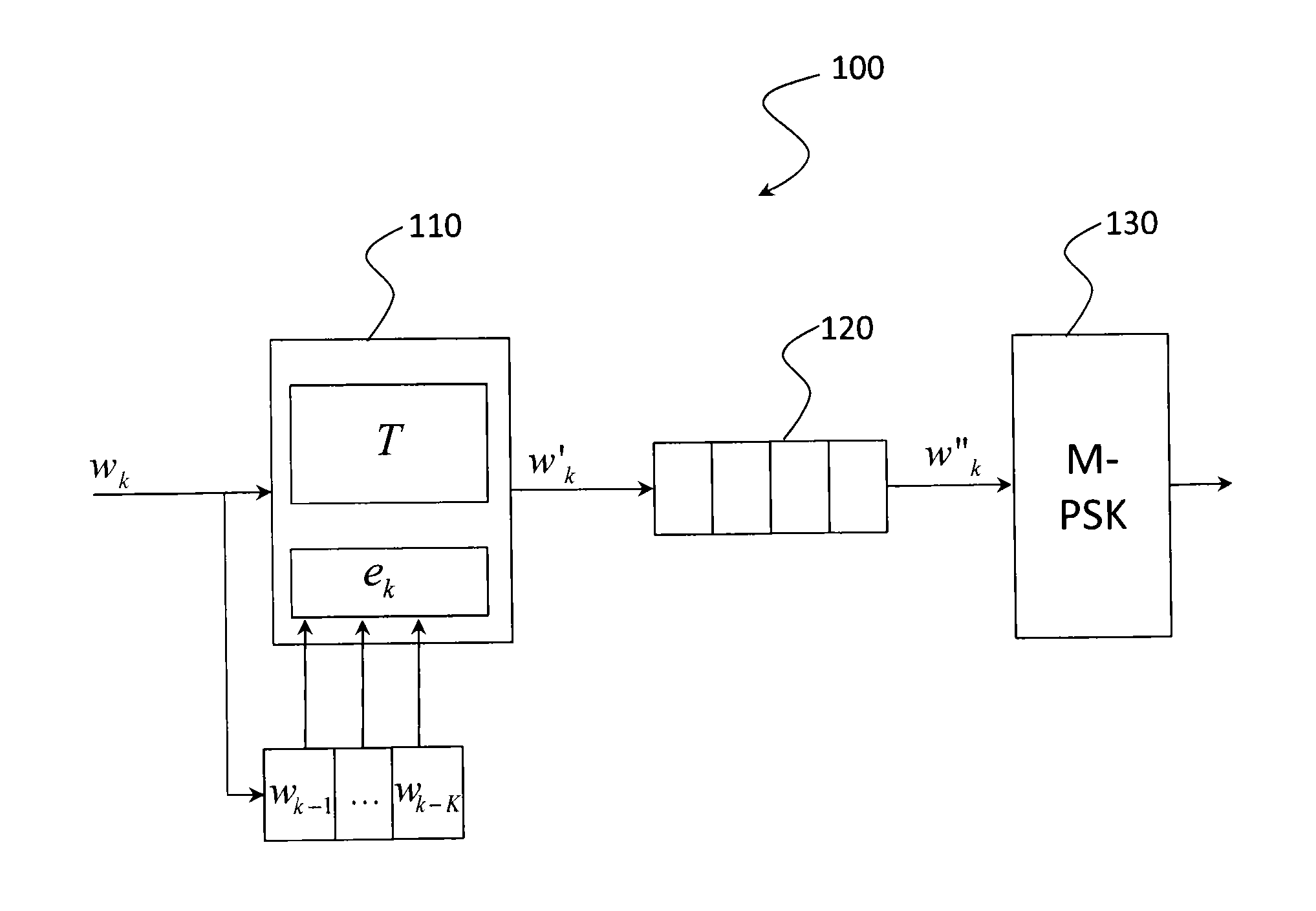
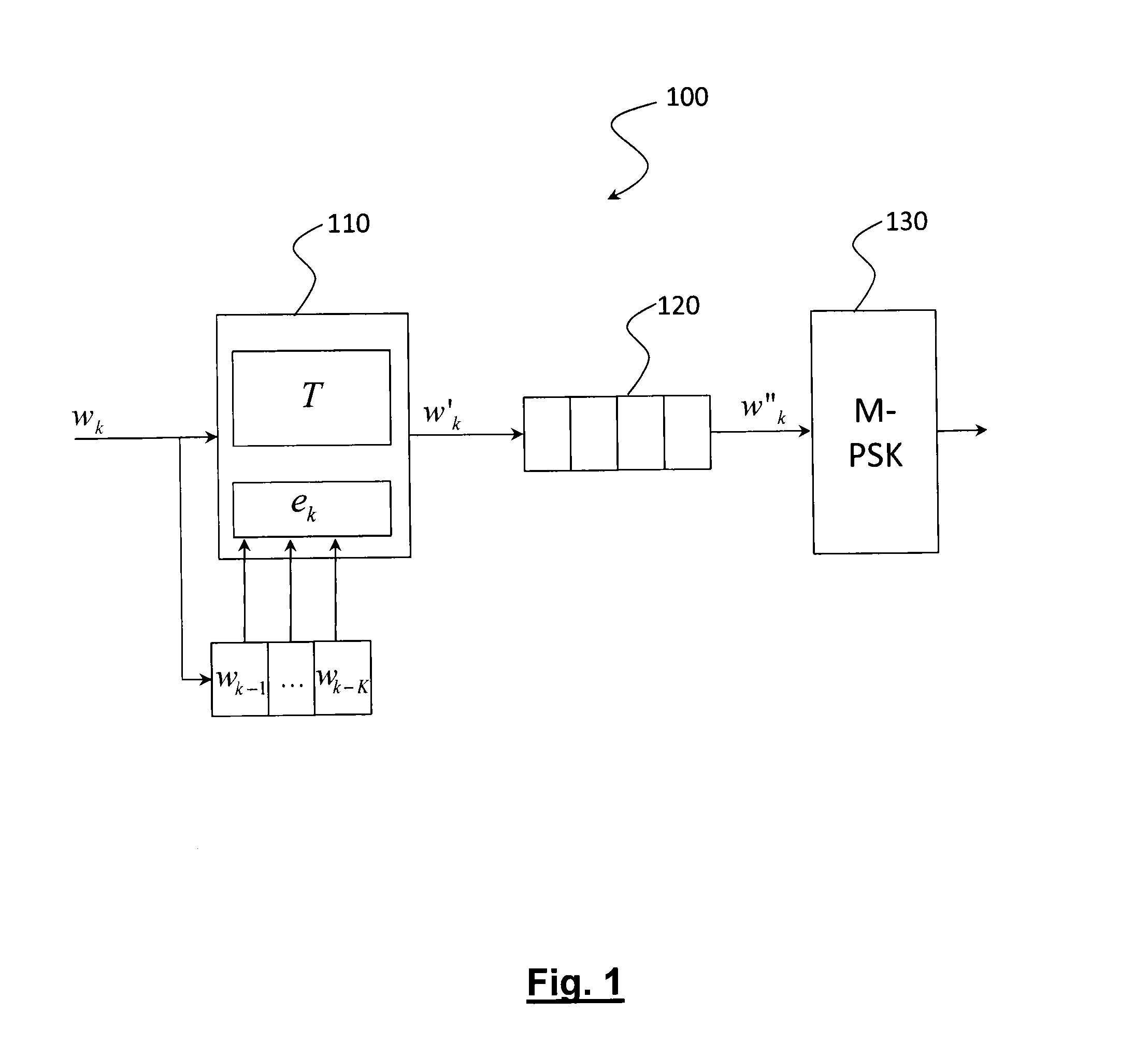
[0033]FIG. 1 represents in a schematic manner a digital modulation device according to the invention;

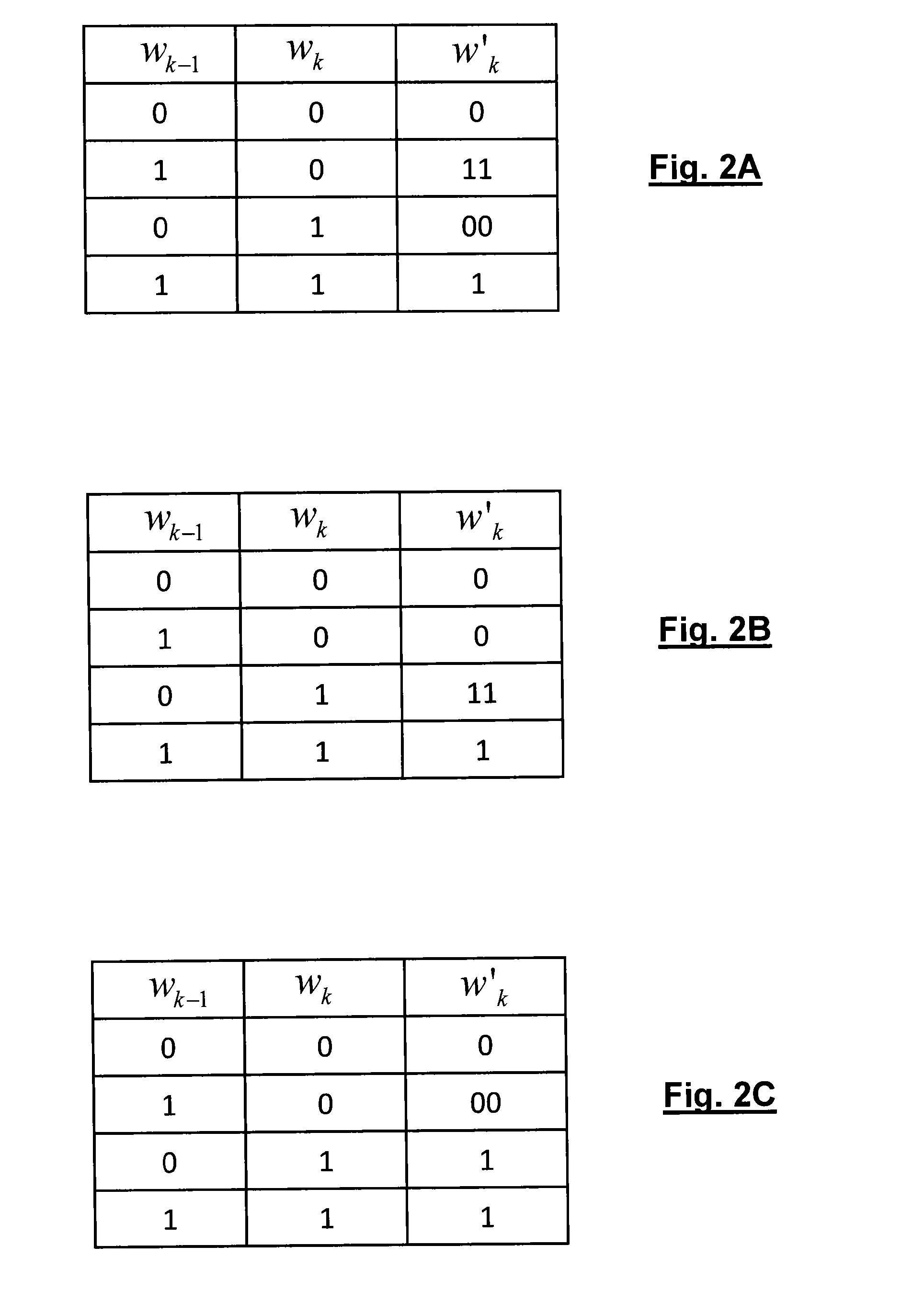
[0034]FIG. 2A represents a first example of transcoding table for the digital modulation device of FIG. 1 when the input words are of 1 bit;

[0035]FIG. 2B represents a second example of transcoding table for the digital modulation device of FIG. 1 when the input words are of 1 bit;

[0036]FIG. 2C represents a third example of transcoding table for the digital modulation device of FIG. 1 when the input words are of 1 bit;

[0037]FIG. 3A represents a fourth example of transcoding table for the digital modulation device of FIG. 1 when the input words are of 2 bits;

[0038]FIG. 3B represents a fifth example of transcoding table for the digital modulation device of FIG. 1 when the input words are of 2 bits.

second embodiment

[0039]FIG. 4 represents in a schematic manner a digital modulation device according to the invention;

[0040]FIG. 5 represents a sixth example of transcoding table for the digital modulation device of FIG. 4.


PUM


Abstract

The present invention relates to a digital modulation method and a corresponding modulator. The modulator comprises a transcoder (110) followed by a FIFO register (120) and a 2-PSK modulator (130). The transcoder codes a binary word of fixed size into a code word of variable size using a transcoding table. The transcoding table codes at least one first binary word, leading to a first number of phase transitions at the output of the modulator, into a second word of size greater than that of the first word, leading to, at the output of the modulator, a second number of phase transitions less than the first number of phase transitions.

Description

TECHNICAL FIELD[0001]The present invention generally speaking relates to the field of digital modulation. It applies more particularly to near field communication systems, such as RFID (Radio Frequency Identification) or NFC (Near Field Communication) systems.PRIOR ART[0002]Near field communication systems (RFID, NFC) are very widespread in the general public.[0003]Initially intended to transfer small amounts of data, these systems henceforth require for certain new applications (transfer of biometric files stored in electronic passports, transfer of image files stored in medical dossiers, etc.) to be able to transmit an important quantity of information in very short times.[0004]Also, within the scope of the ISO 14443 standard relative to contactless identification cards, an evolution of the characteristics of the physical layer making it possible to withstand very high rates (up to 27.12 Mbits / s) has been proposed. More generally, the ISO 14443 standard defines the characteristics...

Claims


Application Information

Patent Timeline
IPC IPC(8): H03C3/02
CPCH03C3/02G06K19/0723H04L1/0042H04L27/2046
Inventor PEBAY-PEYROULA, FLORIANDORE, JEAN-BAPTISTE
Owner COMMISSARIAT A LENERGIE ATOMIQUE ET AUX ENERGIES ALTERNATIVES
Learn More