
Operational stability enhancing device for construction machinery

a technology of stability enhancement and construction machinery, which is applied in the direction of instruments, television systems, transportation and packaging, etc., can solve the problems of deteriorating working efficiency and inability to accurately recognize position information

Inactive Publication Date: 2014-05-01
DOOSAN INFRACORE CO LTD
View PDF28 Cites 45 Cited by
  • Summary
  • Abstract
  • Description
  • Claims
  • Application Information

AI Technical Summary

Benefits of technology

This patent is about a device that improves the stability of construction machinery by automatically controlling or moving it to prevent it from hitting detected objects during operation. The device includes a scanner that scans the surrounding information of the machinery to detect obstacles and a screen region display that shows specific areas of the machinery that need attention. The device can also recognize the target of the operation or avoidance processing and automatically control the machinery to prevent damage to the detected object. Overall, the device enhances operational stability and safety during construction operations.

Problems solved by technology

Accordingly, since the operator needs to operate the construction machinery while looking into a mirror provided in the upper turning body and the like of the construction machinery, or directly visually seeing a corresponding movement path, there is a problem in deterioration of working efficiency.
However, according to an image display device for construction machinery to which the AVM system in the related art is applied, a camera is installed only at a front side of a driver's cabin of the construction machinery, that is, a left-front side of the construction machinery, so that it is impossible to accurately recognize position information on an obstacle, such as electric wires and a telephone pole, present at an upper side of a right-front side, which is a blind spot hidden by a boom, a bucket, and the like, of the construction machinery, thereby causing a problem in that a negligence accident is generated when a boom is up or a turning body is turned to a right side.
Further, in the operational stability enhancing device for construction machinery in the related art, since only an image according to a movement route of construction machinery is simply displayed, there is a problem in that an operator needs to cumbersomely check each monitor, and further, since an operator needs to depend on a feeling about a distance from an obstacle checked through the monitor, there is a problem in that a negligence accident is generated in a case where the operator fails to accurately recognize information about a distance from the obstacle.

Method used


Image

  • Operational stability enhancing device for construction machinery
  • Operational stability enhancing device for construction machinery
  • Operational stability enhancing device for construction machinery

Examples


first exemplary embodiment

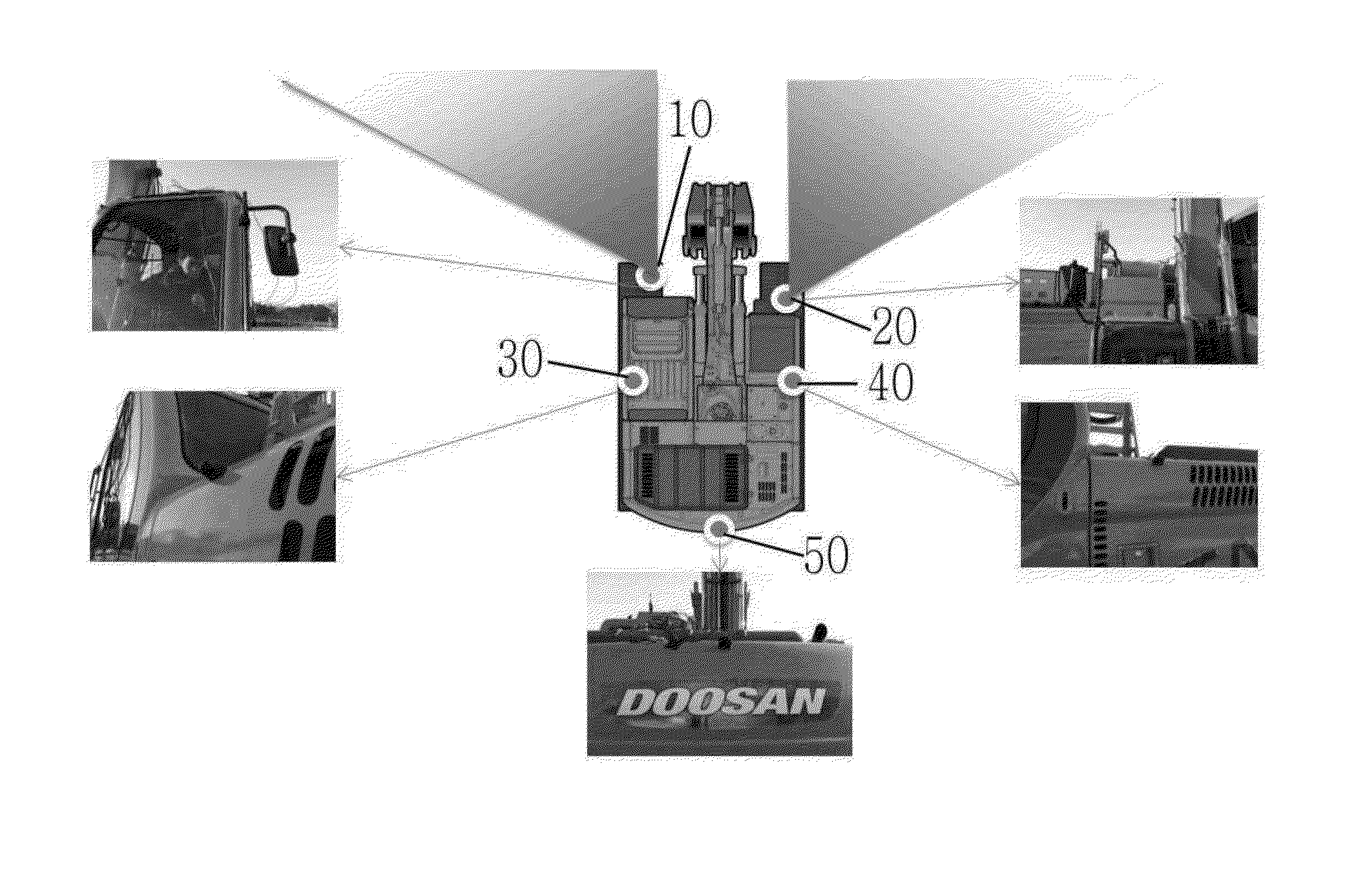
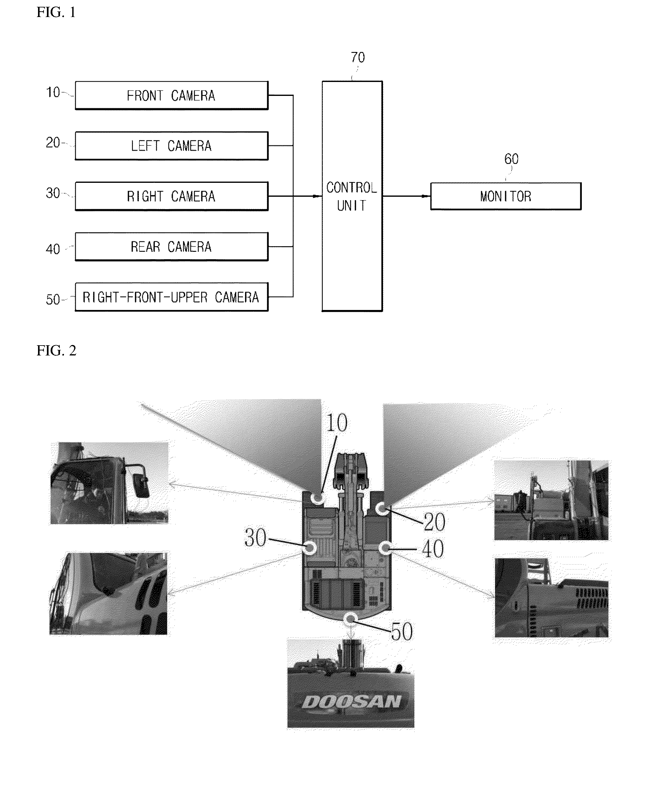
[0031]FIG. 1 is a configuration diagram schematically illustrating a configuration of an image display device for construction machinery according to a first exemplary embodiment of the present disclosure, FIG. 2 is a diagram illustrating the construction machinery to which the image display device of FIG. 1 is applied, and FIG. 3 is a diagram illustrating a scope of an image captured by a right-front camera side in the image display device for the construction machinery of FIG. 1.

[0032]As illustrated in FIGS. 1 to 3, the image display device for construction machinery according to the first exemplary embodiment of the present disclosure includes a front camera 10 positioned at a front side of a driver's cabin of the construction machinery, that is, a front side of the construction machinery, left and right cameras 20 and 30 positioned at left and right sides of the construction machinery, a front-front-upper camera 50 positioned at a right-front side of a turning body of the constr...

second exemplary embodiment

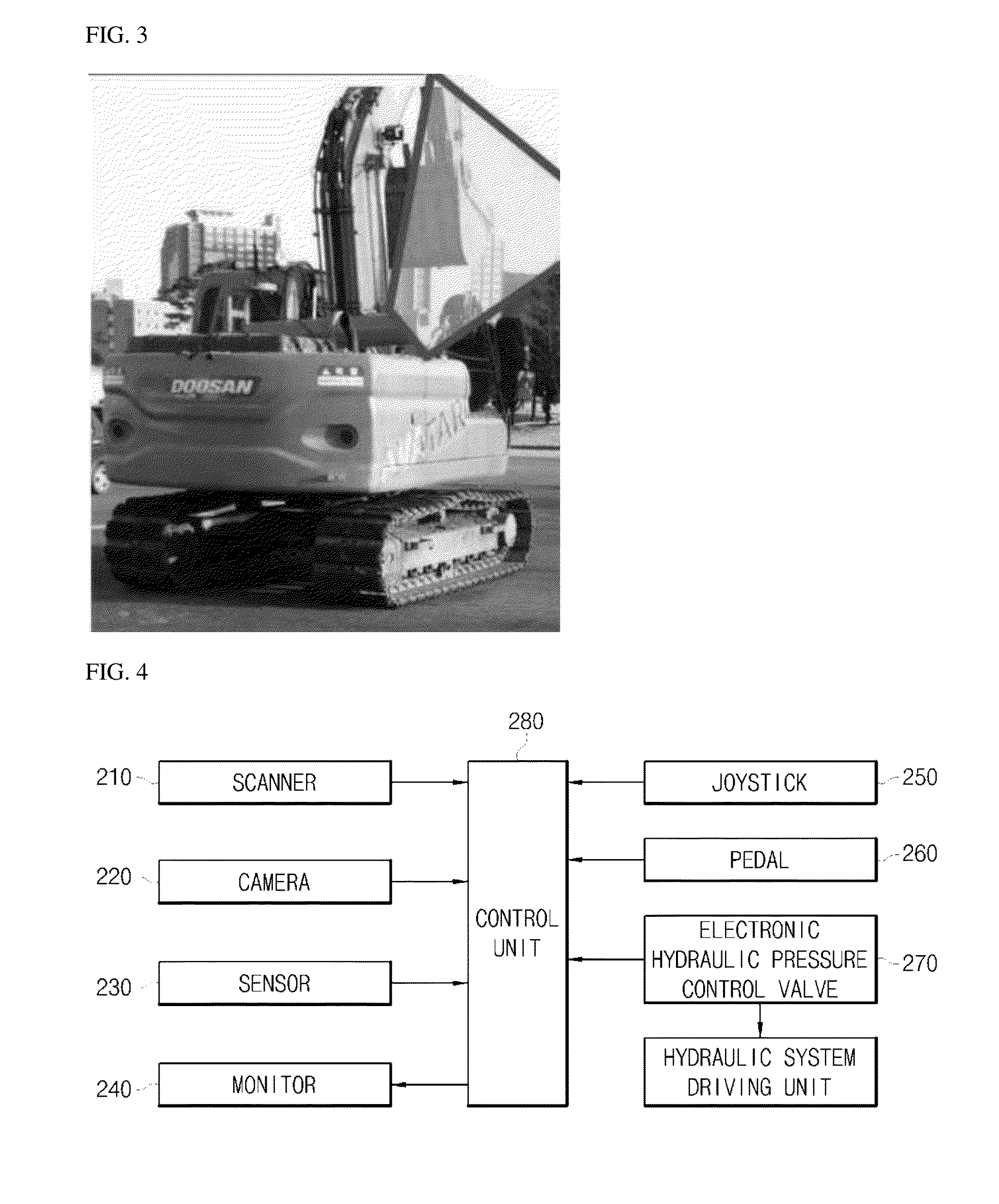
[0050]FIG. 4 is a configuration diagram schematically illustrating a configuration of an operational stability enhancing device for construction machinery according to a second exemplary embodiment of the present disclosure, and FIG. 5 is a control flowchart illustrating a control method of construction machinery according to the operational stability enhancing device of FIG. 4.

[0051]As illustrated in FIGS. 4 and 5, the operational stability enhancing device for construction machinery according to the exemplary embodiment of the present disclosure includes a scanner 210 installed at an upper side of the construction machinery and configured to three-dimensionally scan obstructions scattered in an irregular ground and a field environment, a plurality of cameras 220 provided at a front side, left and right side, a rear side, and the like of the construction machinery and configured to capture the surrounding area of the construction machinery, a plurality of sensors 230 provided at th...


PUM


Abstract

According to the present invention, an operational stability enhancing device for construction machinery is provided. The operational stability enhancing device for construction machinery includes: a plurality of cameras configured to capture surrounding images of construction machinery; a plurality of sensors configured to detect an obstacle located in the surrounding area of the construction machinery; a monitor configured to display the surrounding images captured by the plurality of cameras; and a control unit configured to, in a case where a detected object is detected in a surrounding area of a moving path by the sensor, and the detected object is an avoidance processing target, display an image of the captured detected object on a monitor through screen conversion or change the image of the captured detected object so as to be easily recognized by an operator when the construction machines approaches the detected object.

Description

CROSS-REFERENCE TO RELATED APPLICATION[0001]This application is a Section 371 National Stage application of International Application No. PCT / KR2013 / 000659, filed Jan. 28, 2013 and published, not in English, as WO2013 / 112016 on Aug. 1, 2013.FIELD OF THE DISCLOSURE[0002]The present disclosure relates to an operational stability enhancing device for construction machinery.BACKGROUND OF THE DISCLOSURE[0003]In general, construction machinery, such as an excavator, is constructed such that a lower travelling body and an upper turning body are capable of freely turning. As described above, a case where the upper turning body turns with respect to the lower travelling body or the lower travelling body is reversed is generated while the construction machinery is operated, and in this case, there exists a blind spot which an operator operating the construction machinery in a driver's seat cannot visually see.[0004]Accordingly, since the operator needs to operate the construction machinery wh...

Claims


Application Information

Patent Timeline
IPC IPC(8): B60R1/00
CPCB60R1/00B60R2300/301B60R2300/70E02F9/24E02F9/261G06T3/4038B60R1/27B60R1/28
Inventor CHANG, KYUNG YUL
Owner DOOSAN INFRACORE CO LTD
Learn More