
Active air flap apparatus for vehicle

Active Publication Date: 2014-05-01
HYUNDAI MOTOR CO LTD
View PDF1 Cites 1 Cited by
  • Summary
  • Abstract
  • Description
  • Claims
  • Application Information

AI Technical Summary

Benefits of technology

The invention is an active air flap for vehicles that can reduce pedestrian injuries in accidents. It is designed to rotate and slide when an external force is applied, which meets the safety rules for protecting pedestrians and improves the commercial value of the vehicle.

Problems solved by technology

However, there is a problem that as a large amount of external air flows inside when a vehicle travels at a high speed, the air resistance is considerably large and fuel efficiency of the vehicle reduces.
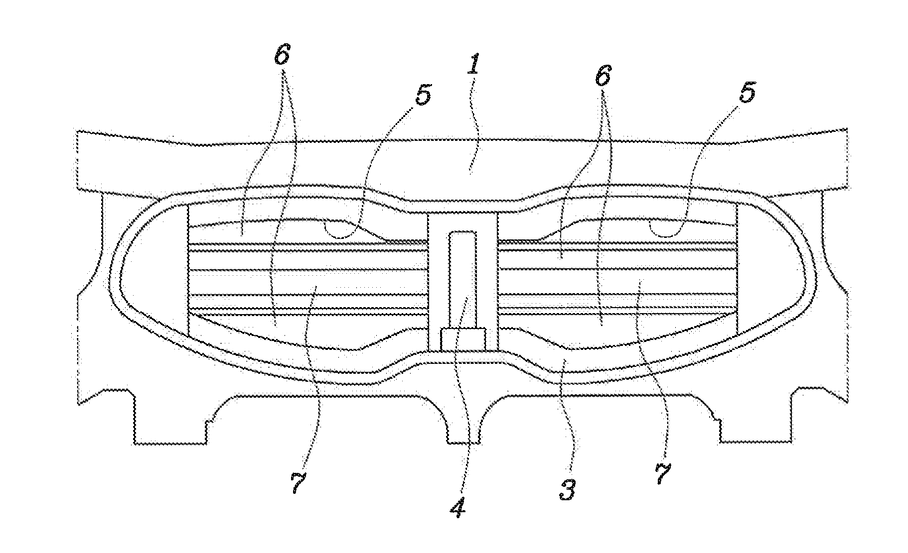
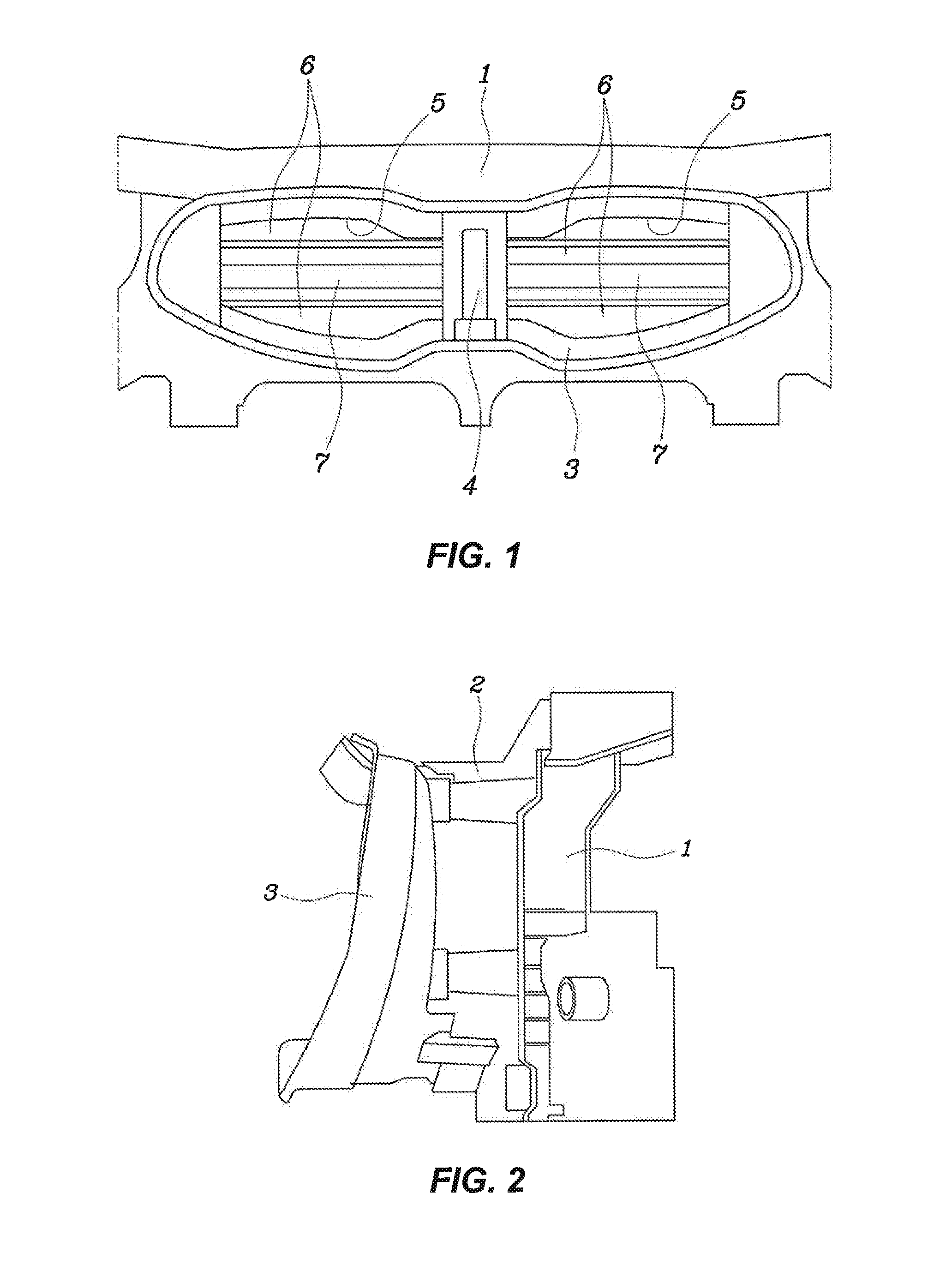
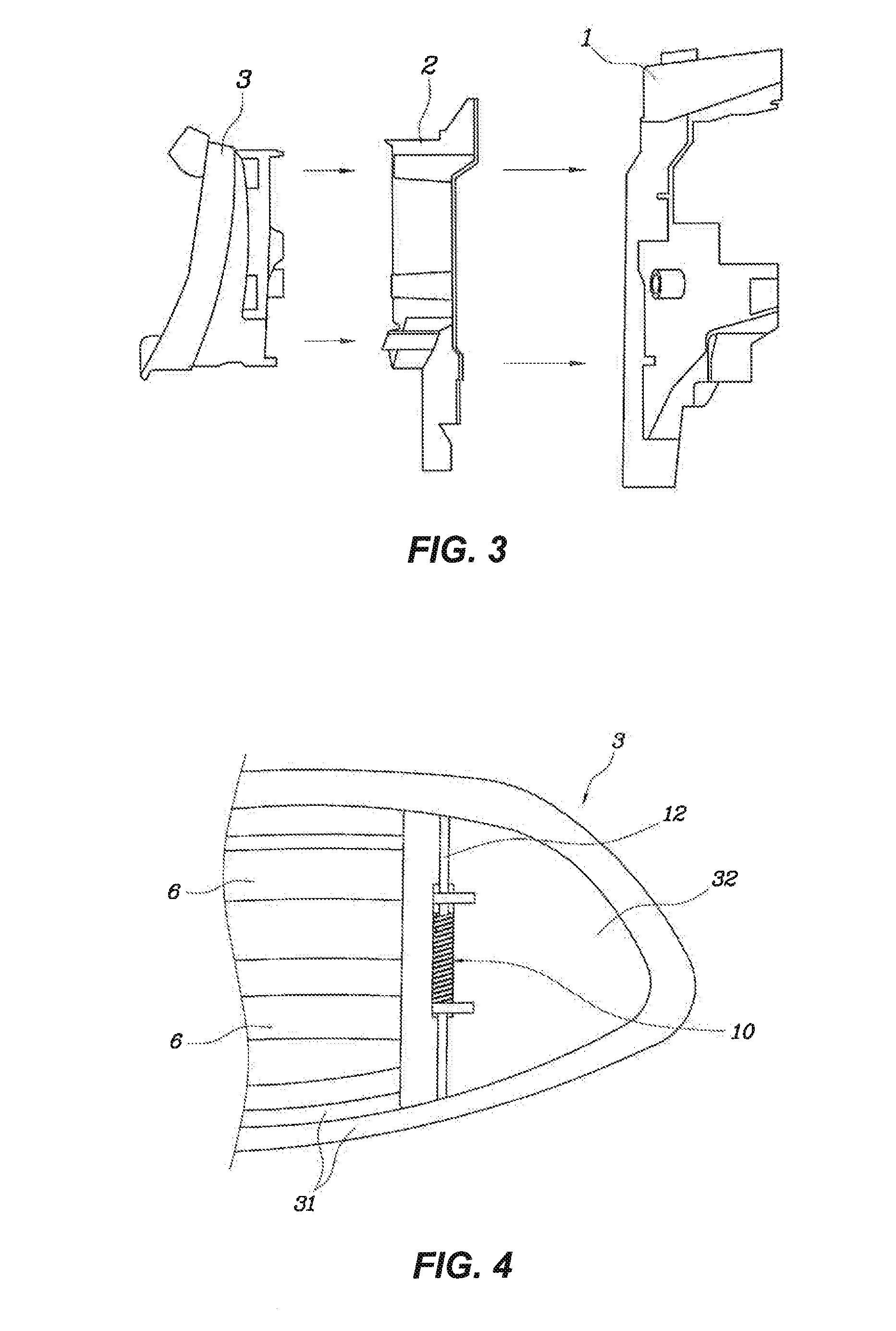
However, there is a defect that the housing 3, which is a rigid body maintaining the external appearance and having rigidity, is fixed not to move with respect to the duct in the active air flap device of the related art described above, so that a pedestrian is more injured in a collision with the pedestrian.

Method used


Image

  • Active air flap apparatus for vehicle
  • Active air flap apparatus for vehicle
  • Active air flap apparatus for vehicle

Examples


Embodiment Construction

[0029]Reference will now be made in detail to various embodiments of the present invention(s), examples of which are illustrated in the accompanying drawings and described below. While the invention(s) will be described in conjunction with exemplary embodiments, it will be understood that present description is not intended to limit the invention(s) to those exemplary embodiments. On the contrary, the invention(s) is / are intended to cover not only the exemplary embodiments, but also various alternatives, modifications, equivalents and other embodiments, which may be included within the spirit and scope of the invention as defined by the appended claims.

[0030]It is understood that the term “vehicle” or “vehicular” or other similar term as used herein is inclusive of motor vehicles in general such as passenger automobiles including sports utility vehicles (SUV), buses, trucks, various commercial vehicles, watercraft including a variety of boats and ships, aircraft, and the like, and i...


PUM


Abstract

An active air flap for a vehicle can absorb shock energy by means of a wing of a housing which pivots in a collision with a pedestrian and can minimize the pedestrian injury as possible.

Description

CROSS-REFERENCE TO RELATED APPLICATION[0001]The present application claims priority of Korean Patent Application Number 10-2012-0122374 filed Oct. 31, 2012, the entire contents of which application is incorporated herein for all purposes by this reference.BACKGROUND OF INVENTION[0002]1. Field of Invention[0003]The present invention relates to an active air flap apparatus for a vehicle, and more particularly an active air flap apparatus for a vehicle which has a pedestrian protection function.[0004]2. Description of Related Art[0005]In general, not only the parts for driving such as an engine, but various heat exchangers such as a radiator, an intercooler, an evaporator, and a condenser are disposed in the engine compartment of vehicles.[0006]These heat exchangers allow a refrigerant to flow through them and are cooled or discharge heat by means of heat exchange between the refrigerant in the heat exchangers and air outside the heat exchangers, and the external air should be supplied...

Claims


Application Information

Patent Timeline
IPC IPC(8): B62D35/00
CPCB62D35/00Y02T10/88B60K11/085B62D25/08B60K11/06
Inventor YOO, GIL SANG
Owner HYUNDAI MOTOR CO LTD
Learn More