
Mechanical Device for the Seismic Protection of Civil Works

a mechanical device and seismic protection technology, applied in the direction of mechanical equipment, machine supports, shock-proofing, etc., can solve the problems of affecting the seismic protection effect of civil works, affecting the calculation of the cross section of the element which eventually has to break, and the device may rest in the blockage, so as to achieve the effect of mitigating the seismic vibration

Inactive Publication Date: 2014-05-01
FCC CONSTR SA
View PDF6 Cites 2 Cited by
  • Summary
  • Abstract
  • Description
  • Claims
  • Application Information

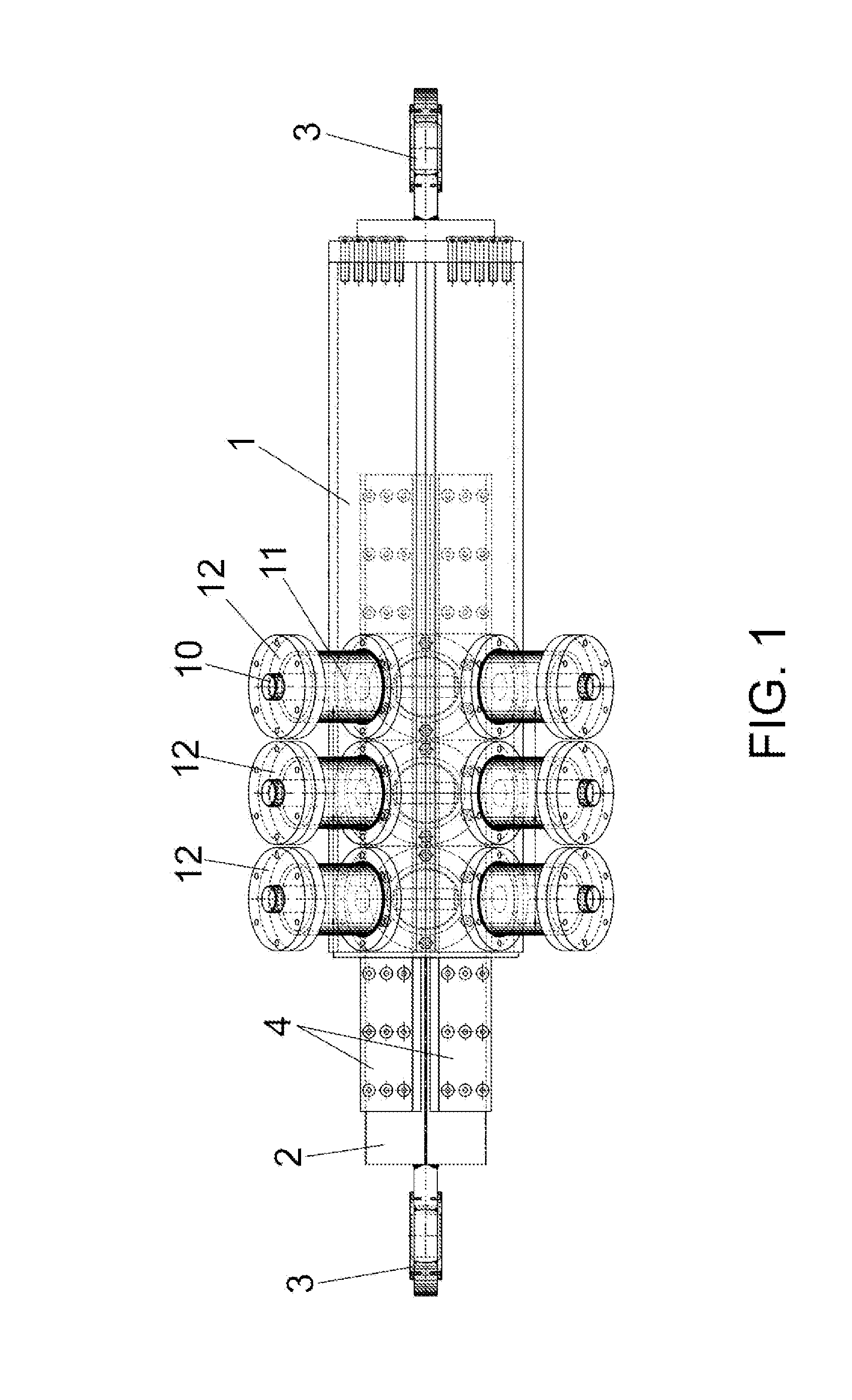
AI Technical Summary

Benefits of technology

The invention describes a device that can be installed in structures to help reduce the damage caused by seismic vibrations. The device is designed to withstand high levels of force without wearing down or needing maintenance, and can be reused. This makes it easier to protect buildings and other structures from seismic risks.

Problems solved by technology

The problem arising from this type of devices is that they not only work under circumstances of seismic activity, but they function as well under normal loads from traffic, wind or temperature, which provokes wear as well as the need of carrying out continuous maintenance operations, for example, the change / reposition of the oil / silicone, the change of worn out parts, etc.
The problem with this type of devices, besides the fact that once the breakage has taken place the device becomes unusable, being necessary to substitute at least the axial blocking means; consists in that the surface of the breakage of this type of materials is frequently not sufficiently clean, so that, once the breakage has taken place, the displacement in one sense is free, in the movement in the contrary direction of return provoked by the seismic vibration, the device may rest blocked, given the irregularities of the breakage surface with the subsequent unsatisfactory working of the same.
Another type of problem of these devices is that the calculation of the cross section of the element which eventually has to break is usually not easy and in any case, the device is designed to meet a determined breaking effort which cannot be adjusted or tested without having to substitute the device for a new one.

Method used


Image

  • Mechanical Device for the Seismic Protection of Civil Works
  • Mechanical Device for the Seismic Protection of Civil Works
  • Mechanical Device for the Seismic Protection of Civil Works

Examples


Embodiment Construction

[0010]The mechanical protection device provided by the invention solves in a fully satisfactory manner the above explained problems thanks to a very effective new structure which does not need any type of maintenance, being easily adjustable to different effort values according to the specific needs in each case.

[0011]In this connection, the device of the invention starts from a telescopic structure having two arms, one of them displaceable within the other, both having corresponding attachment means with the peculiarity that the arm with a lower cross section, that is, the arm which is displaceable within the arm with a larger cross section, has multiple grooves in a sense perpendicular to the displacement, which grooves in the normal working situation stand opposite to other grooves of the same size arranged in the arm with larger cross section. Both sets of grooves are blocked by a rigid element, preferably a cylinder which, depending on the axial load to which it is submitted, m...


PUM


Abstract

The device of the invention consists in a telescopic element with two arms, one of them movable within the other, having in its corresponding ends attachment means (3), so that the shorter arm (2) has means with an axial groove (5) which in the normal working situation is operatively opposite in respect to an axial chamber (6) of the internal portion of the longer arm (1), so that in said chamber a blocking element is movable vertically in respect to the groove, preferably a cylinder (7) opposing the effort of an elastic element located within the corresponding housing (11) which is encased in said groove (5) blocking the device and permitting its unblocking once the effort of the elastic means on the cylinder is exceeded. The device is reusable and it is easily adjustable to different levels of effort for its unblocking.

Description

OBJECT OF THE INVENTION[0001]The invention refers to a device which has been specially designed for its installation in structures of civil works, in parallel to a number of dampers, in order to mitigate the effects produced by seismic vibrations.[0002]The aim of the invention is to provide a mechanical device to permit the actuation of other devices once exceeded a predetermined effort level, which may be easily adjusted, without wear or maintenance problems, having as well a reusable character.BACKGROUND OF THE INVENTION[0003]Within the field of the practical application of the invention that is, civil work structures, various types of dampers are known for seismic engineering, which act as union elements between two structures which must stay without relative movement in the normal work situation but which in front of high efforts produced by seismic effects must permit the displacement between said structures in order to absorb the vibrations with the assistance of a number of d...

Claims


Application Information

Patent Timeline
IPC IPC(8): E04B1/98F16F3/00
CPCE04B1/98F16F3/00E04H9/0235F16F15/04
Inventor POYATOS, JOSE LUIS ALVAREZSALCEDO, JOSE MARTINEZ
Owner FCC CONSTR SA
Learn More