
Variable compression ratio engine

a compression ratio and engine technology, applied in the direction of engines, machines/engines, engine controllers, etc., can solve the problems of fuel igniting, limited compression ratio, engine damage,

Active Publication Date: 2014-05-01
BLACKSTOCK SCOTT
View PDF7 Cites 20 Cited by
  • Summary
  • Abstract
  • Description
  • Claims
  • Application Information

AI Technical Summary

Benefits of technology

The present invention provides a system and method for adjusting the compression ratio of an internal combustion engine. The system includes a cylinder head / block assembly and a crankcase, which can move vertically to change the distance between the head and the crankshaft, while being prevented from movement in other directions. The movement of the assembly can be controlled by a control system. In some embodiments, locating pins and holes in the assembly can enable the assembly to move in the vertical direction. The technical effect of the invention is to provide a system that enables adjustment of the compression ratio of an internal combustion engine without significantly impacting its performance.

Problems solved by technology

In a gasoline engine, however, increasing the compression ratio is limited by pre-ignition and / or “knocking.” In other words, if the compression ratio is high enough then, like a diesel, the compression of the fuel causes it to ignite (or, “pre-ignite) before the spark plug fires.
This can result in damage to the engine because cylinder temperatures and pressures spike as the fuel / air mixture explodes on multiple fronts, rather than burning uniformly.
The maximum acceptable compression ratio in an engine is limited by a number of factors including, but not limited to, combustion chamber and piston design, cylinder and piston cooling, engine loading, and air temperature and humidity.
Due to difficulties associated with reliably moving components in an operating internal combustion engine, however, all currently mass produced engines operate with a fixed compression ratio.
As a result, the stock compression ratio tends to be a compromise between a high-compression ratio, which is more efficient—but can result in the aforementioned knocking—and a low compression ratio engine—which is more forgiving of, for example, poor quality fuels, high loads, and / or high temperatures.
Prior inventions based on raising and lowering the cylinder block / head assembly relative to the crankcase have not been practical for use in moving vehicles, however.
Prior inventions allowed the cylinder block / head assembly to move in substantially all directions (i.e., as opposed to limiting movement to the Y axis, or perpendicular to the crankshaft), resulting in severe side loading and premature component failure.
Other previous mechanisms have separated the cylinder sleeve from the crankcase, used heavy control mechanisms, or have prevented the location of engine mounts above the center of gravity of the engine leading to stability issues.

Method used


Image

  • Variable compression ratio engine
  • Variable compression ratio engine
  • Variable compression ratio engine

Examples


example 1

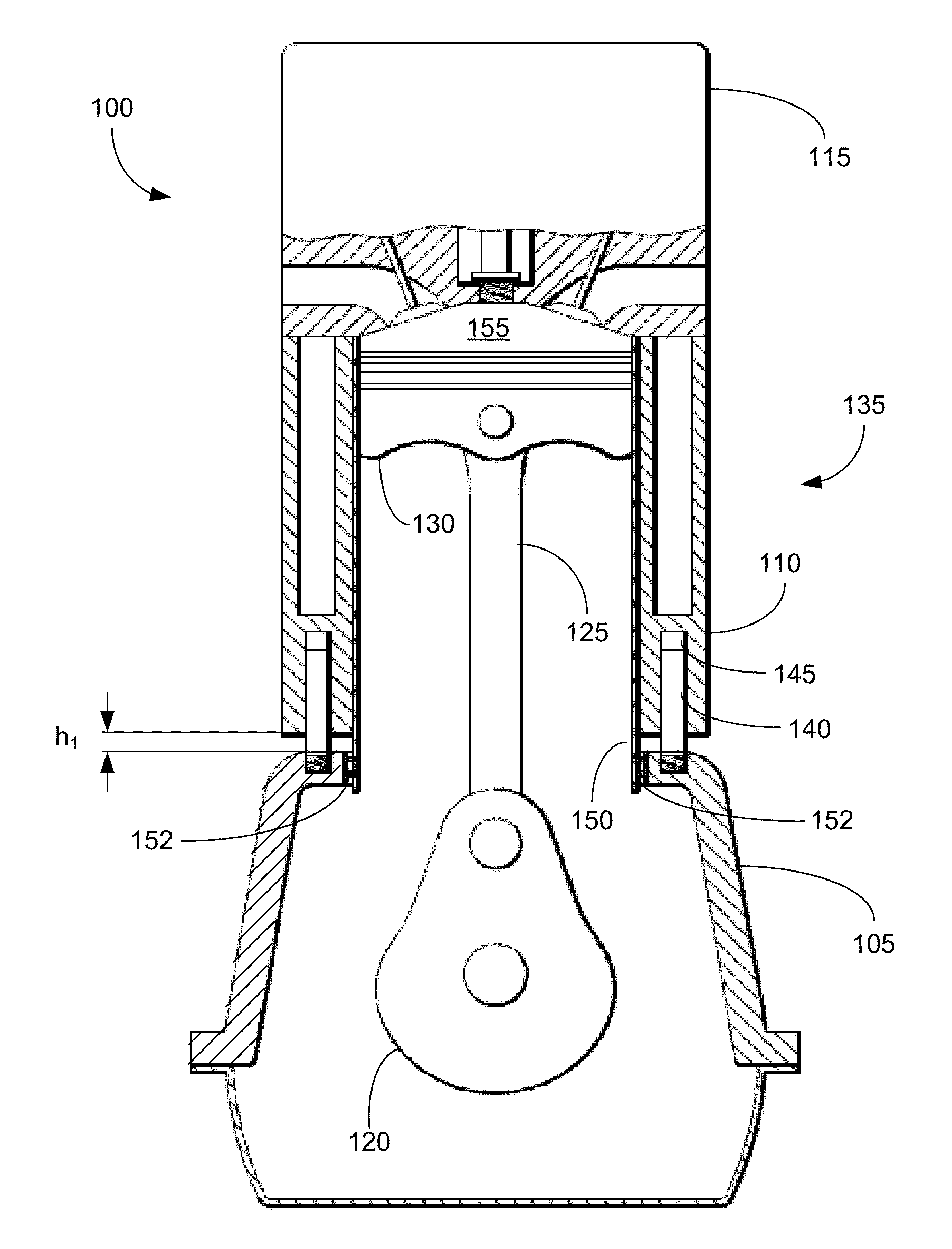
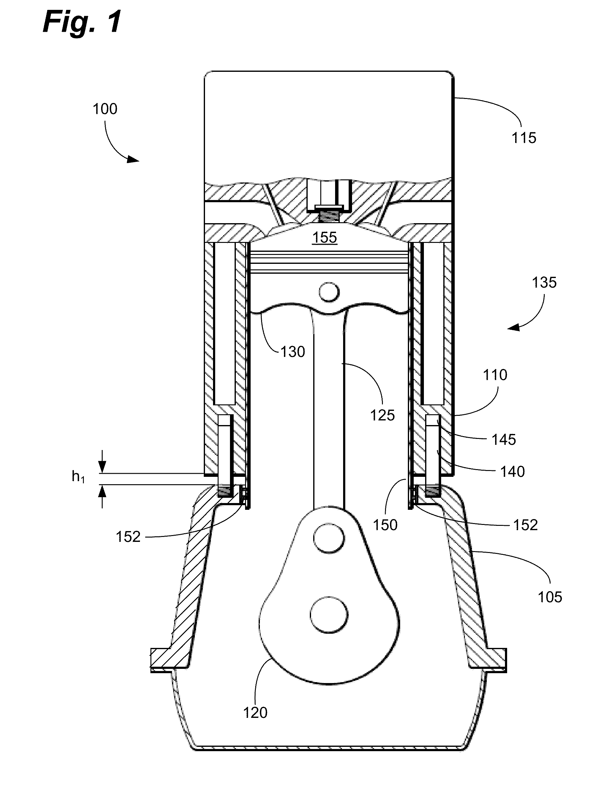
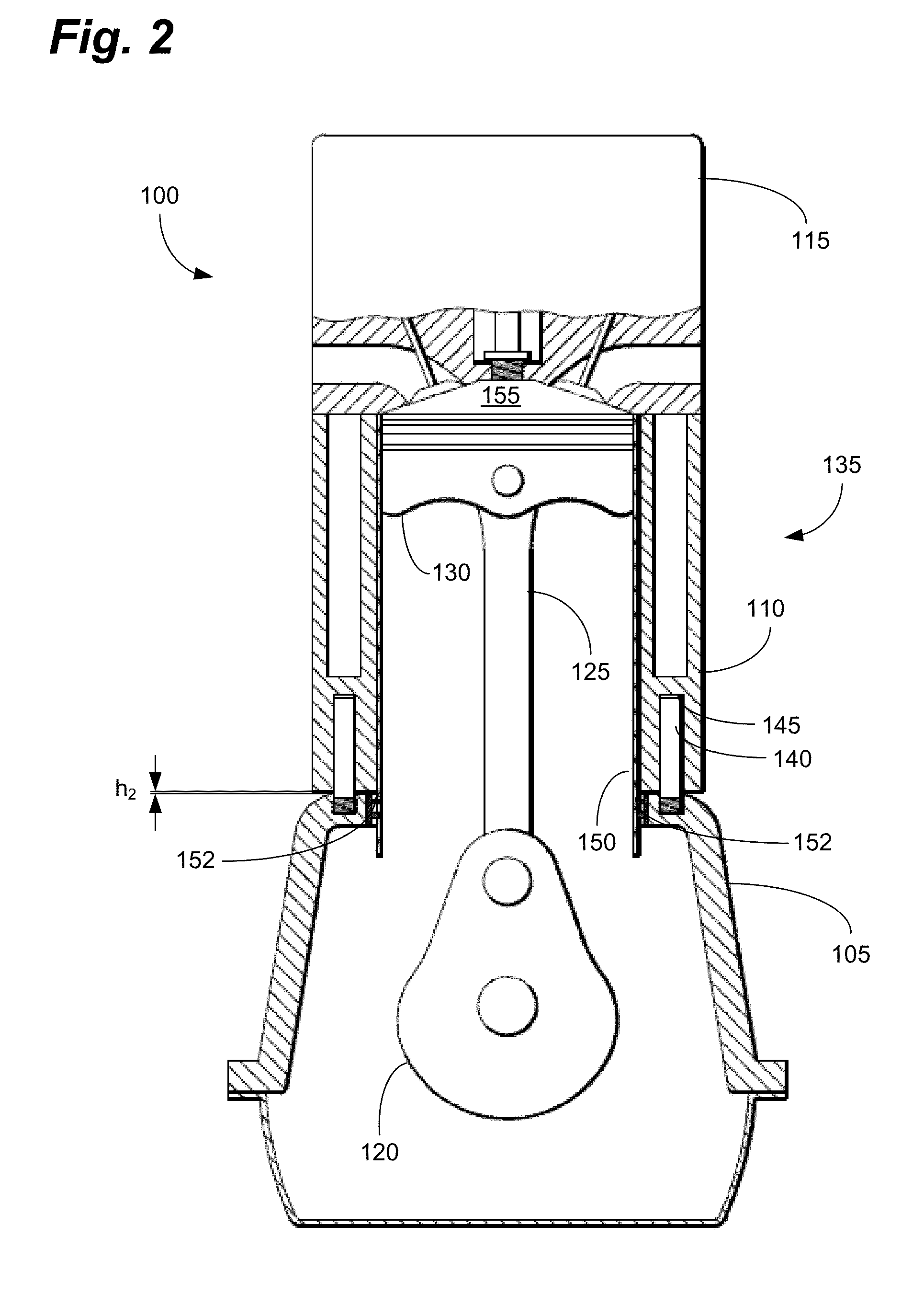
[0076]As mentioned above, FIG. 1 depicts the VCRE 100 in a low-compression position (LCR) in which the head / block assembly 135 is a distance h1 from the crankcase 105 (and thus, the crankshaft 120). This increases the volume of the combustion chamber 155 and lowers the compression ratio. Similarly, FIG. 2 depicts the VCRE 100 in a high-compression configuration (HCR) in which the height h2 between the head / block assembly 135 and the crankcase 105 has been reduced (or eliminated). This decreases the volume of the combustion chamber 155 and raises the compression ratio. As discussed below, a surprisingly small change in this height h has a significant effect on compression ratio.

[0077]For simplicity, assume the VCRE 100 has a stroke of 4 inches and a regular, cylindrical shape. Assume a compression ratio of 10 to 1 with 0.4 inches effective combustion chamber height when the cylinder head is in a “neutral” position (i.e., halfway between h1 and h2). In this configuration, if the h2 is...


PUM


Abstract

A system and method for providing a variable compression ratio internal combustion engine is disclosed. The system can include a frame affixed to the engine crankcase and a complementary frame affixed to the block / cylinder head assembly. The system can further comprise an actuating system to enable the block / head assembly to be moved up and down with respect to the crankcase, varying the compression ratio of the engine. A number of mechanisms can be used to achieve this movement, including a rack and pinion, a hydraulic or pneumatic actuator, and a gear drive. The compression ratio can be varied continuously during use. The frames substantially limit movement of the engine components to the y-axis, thus reducing, or eliminating, unwanted movement and stresses in other directions.

Description

CROSS REFERENCE TO RELATED APPLICATIONS[0001]This application claims priority to and benefit under 35 USC §119(e) of U.S. Provisional Patent Application Ser. Nos. 61 / 720,113, filed Oct. 30, 2012, and 61 / 772,987, filed Mar. 5, 2013, both entitled “Variable Compression Engine.” Both applications are hereby incorporated by reference as if fully set forth below.BACKGROUND OF THE INVENTION[0002]1. Field of the Invention[0003]Embodiments of the present invention relate generally to internal combustion engines and, specifically to internal combustion engines with mechanisms for varying the compression ratio.[0004]2. Background of Related Art[0005]In a reciprocating internal combustion engine, the compression ratio of an engine is defined as the ratio between the free volume of the cylinder when the piston is at bottom-dead-center (BDC) to the free volume when the piston is at top-dead-center (TDC). All other things being equal, engines tend to be more efficient and produce more power when ...

Claims


Application Information

Patent Timeline
Patent Type & Authority Applications(United States)
IPC IPC(8): F02B75/04
CPCF02B75/04F02B75/041F02D15/04F02D2700/03
Inventor BLACKSTOCK, SCOTT
Owner BLACKSTOCK SCOTT
Learn More