
Method and system to reduce system boot loader download time for spi based flash memories

a technology of flash memory and system boot loader, applied in the direction of digital storage, memory adressing/allocation/relocation, instruments, etc., can solve the problems of inability to operate the memory, device frequency,

Inactive Publication Date: 2014-04-24
AVAGO TECH WIRELESS IP SINGAPORE PTE
View PDF4 Cites 677 Cited by
  • Summary
  • Abstract
  • Description
  • Claims
  • Application Information

AI Technical Summary

Benefits of technology

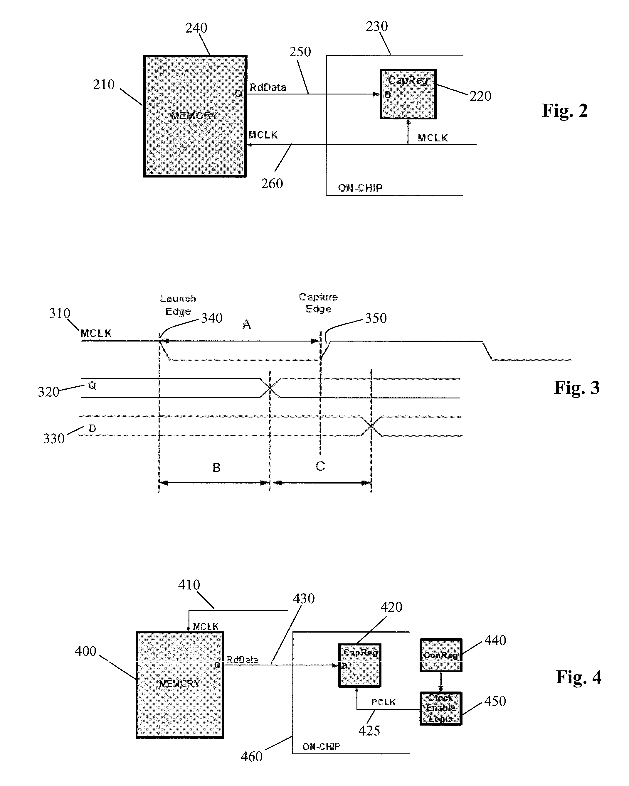
The present invention relates to a system that allows for efficient capturing of data from flash memories connected to other components (e.g., processors) within electronic systems. This is achieved through use of a flash memory that operates based on its own internal clock and a separate capture register that also operates based on another external clock. By aligning these two clocks, data can be efficiently collected without causing any delays or errors during processing.

Problems solved by technology

The technical problem addressed by this patent relates to improving the performance of flash memories connected through a Serial Peripheral Interface (SPI) bus. Due to limitations such as clock speed restrictions and signal timing issues, current methodologies result in slow operation of the flash memories compared to their rated frequency. This issue affects overall system performance and needs to be solved to improve efficiency and reliability.

Method used


Image

  • Method and system to reduce system boot loader download time for spi based flash memories
  • Method and system to reduce system boot loader download time for spi based flash memories
  • Method and system to reduce system boot loader download time for spi based flash memories

Examples


Embodiment Construction

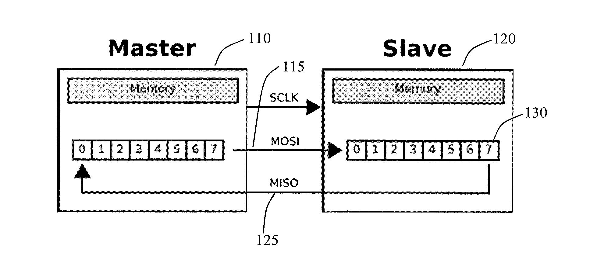
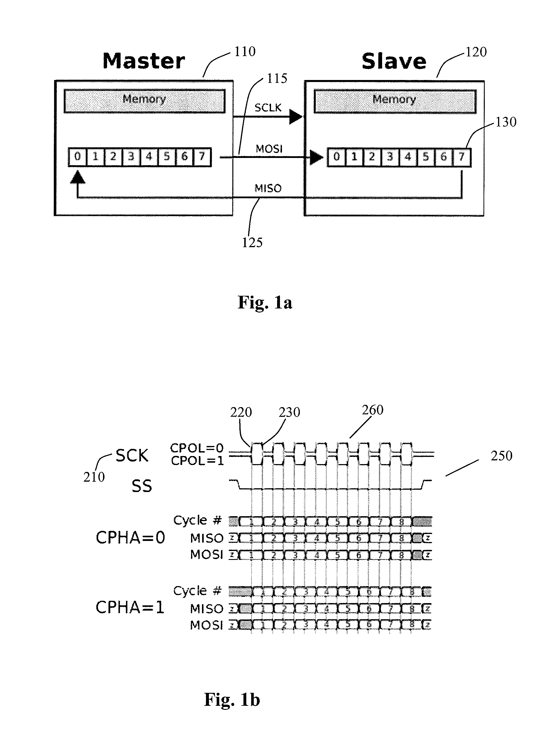
[0010]FIG. 1a shows a hardware setup using two shift registers to form an inter-chip circular buffer, as an example of an SPI master / slave configuration. To begin a communication, the bus master first configures the clock, using a frequency less than or equal to the maximum frequency the slave device supports. During each SPI clock cycle, a full duplex data transmission will occur. This means that the master 110 will send a bit on the MOSI line 115—and the slave 120 will read it from that same line. The slave will send a bit on the MISO line 125 and the master will read if from that same line. It is understood that not all transmissions require all four of these operations.

[0011]Transmissions may involve two shift registers 130 of some given word size, such as 8 bits. One register 130 is in the master 110 and one register is in the slave 120. Transmissions may involve any number of clock cycles. When data has completed transmission, the master 110 will stop toggling its clock.

[0012]...


PUM


Abstract

Method and system for providing increased frequency of flash memories compatible to Serial Peripheral Interface (SPI) bus protocol by delayed data capturing so that system boot loader down load time reduces for a given memory configuration. Methods and systems are provided for operating the memory at the device rated frequency.

Description


Claims


Application Information

Patent Timeline
Owner AVAGO TECH WIRELESS IP SINGAPORE PTE
Learn More