Variable-magnification projection optical system and projection display device
a projection optical system and variable magnification technology, applied in the field of variable magnification projection projection optical system and projection display device, can solve the problems of low zoom ratio of the zoom lens of patent document 2, short back focus and low zoom ratio, etc., to minimize the size increase of the entire system, high zoom ratio, and high versatility
- Summary
- Abstract
- Description
- Claims
- Application Information
AI Technical Summary
Benefits of technology
Problems solved by technology
Method used
Image
Examples
example 2
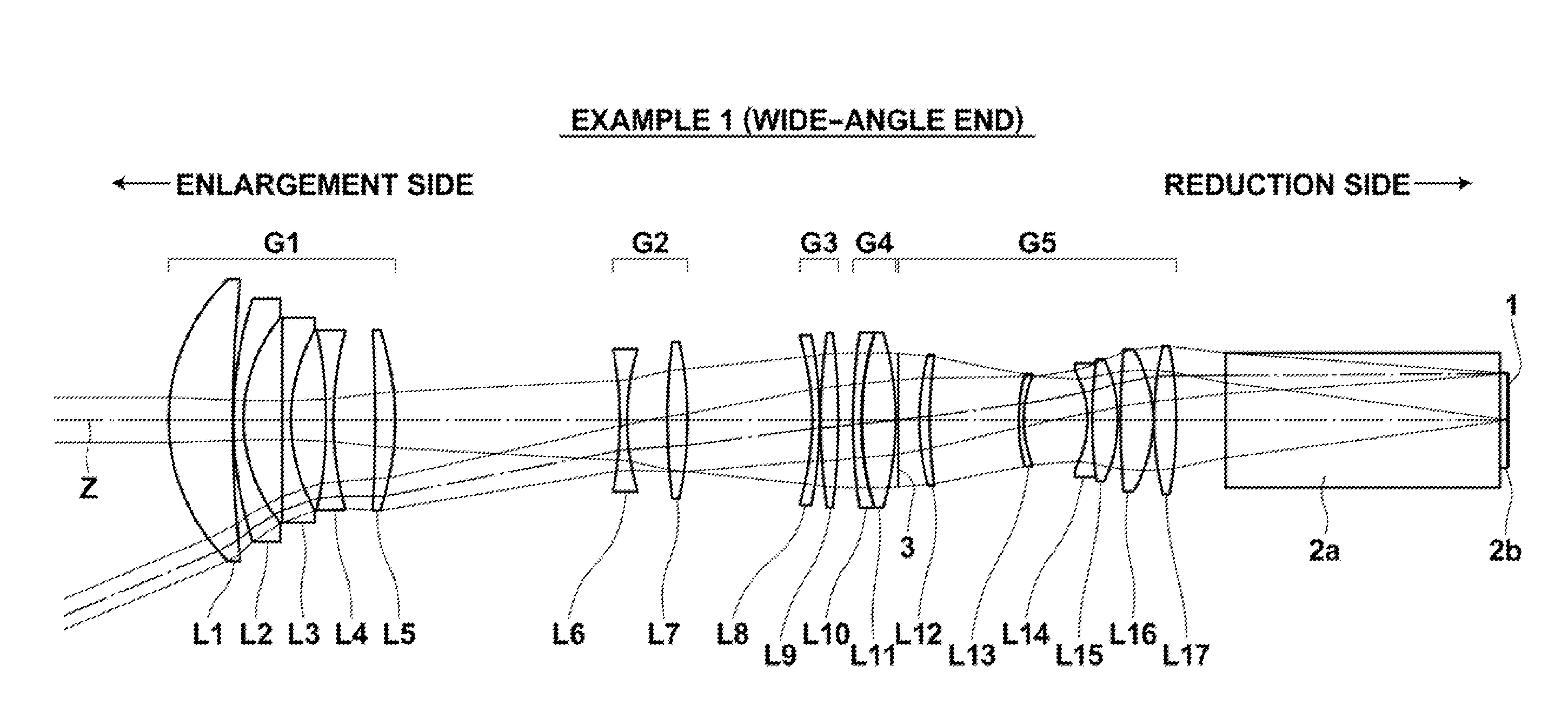
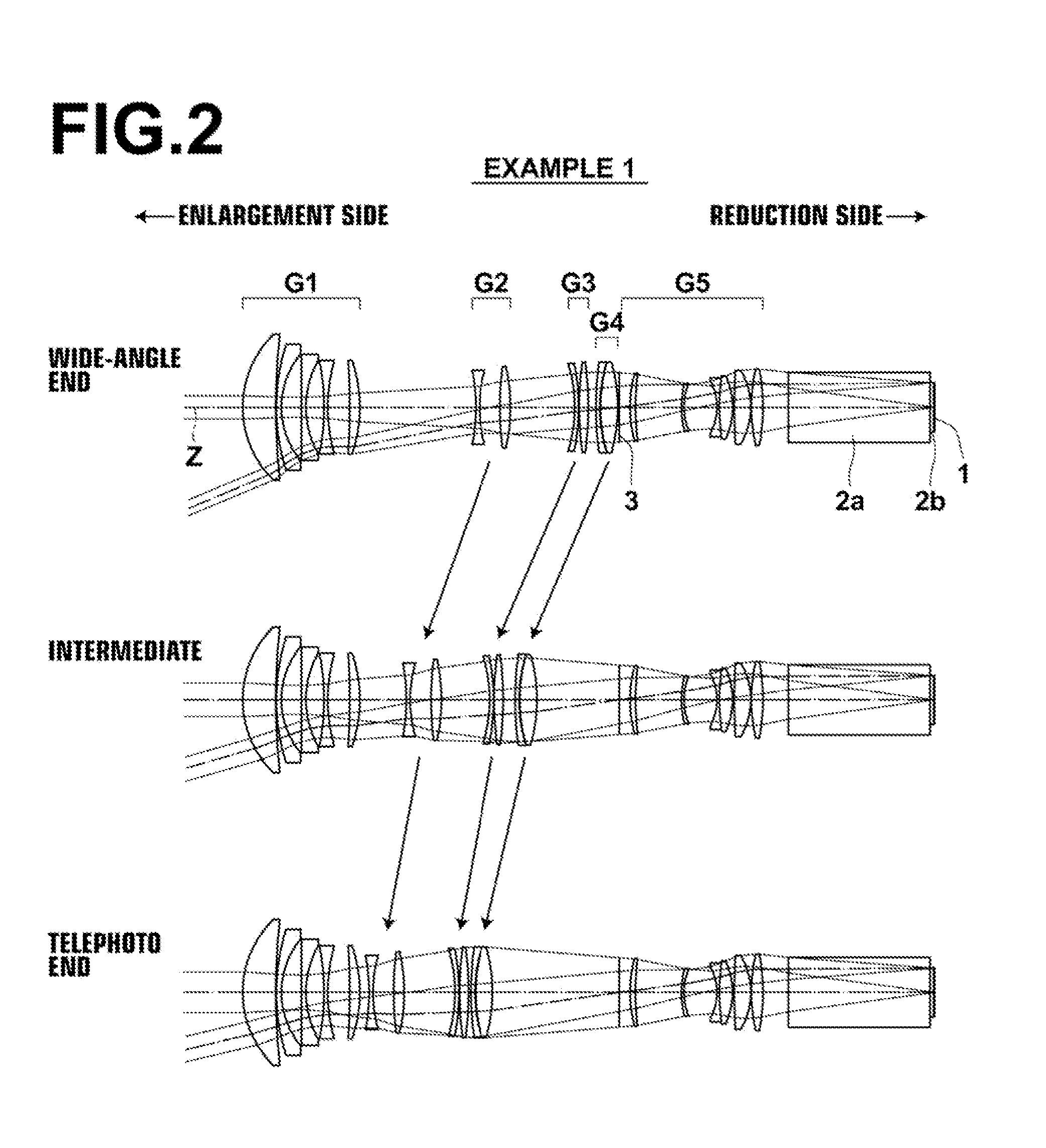
[0115]FIGS. 3 and 4 show the lens configuration and ray trajectories at the wide-angle end of the variable-magnification projection optical system of Example 2, and positions of the lens groups and ray trajectories in different magnification positions of the variable-magnification projection optical system of Example 2, respectively. The configuration of the variable-magnification projection optical system according to Example 2 is substantially the same as that of the variable-magnification projection optical system according to Example 1, except that the fifth lens L5 of the first lens group G1 is formed by a biconvex lens, and the seventh lens L7 of the second lens group G2 is formed by a positive meniscus lens with the convex surface facing the reduction side.
[0116]The f-number “Fno.” and the total angle of view “2ω” of the variable-magnification projection optical system of Example 2 are shown above Table 2, the basic lens data is shown in the upper table of Table 2, and the va...
example 3
[0117]FIGS. 5 and 6 show the lens configuration and ray trajectories at the wide-angle end of the variable-magnification projection optical system of Example 3, and positions of the lens groups and ray trajectories in different magnification positions of the variable-magnification projection optical system of Example 3, respectively. The configuration of the variable-magnification projection optical system according to Example 3 is substantially the same as that of the variable-magnification projection optical system according to Example 1, except that the fifth lens L5 of the first lens group G1 is formed by a biconvex lens, and the seventh lens L7 of the second lens group G2 is formed by a positive meniscus lens with the convex surface facing the reduction side.
[0118]The f-number “Fno.” and the total angle of view “2ω” of the variable-magnification projection optical system of Example 3 are shown above Table 3, the basic lens data is shown in the upper table of Table 3, and the va...
example 4
[0119]FIGS. 7 and 8 show the lens configuration and ray trajectories at the wide-angle end of the variable-magnification projection optical system of Example 4, and positions of the lens groups and ray trajectories in different magnification positions of the variable-magnification projection optical system of Example 4, respectively. The symbol (positive or negative) of the refractive power of each of the first to the fifth lens groups G1 to G5, the lens groups that are fixed during magnification change, and the lens groups that are moved during magnification change of the variable-magnification projection optical system according to Example 4 are the same as those of the variable-magnification projection optical system according to Example 1. The variable-magnification projection optical system of Example 4 differs from the variable-magnification projection optical system of Example 1 in that the lens groups of the variable-magnification projection optical system of Example 4 have ...
PUM
 Abstract
Description
Claims
Application Information
 - R&D
- Intellectual Property
- Life Sciences
- Materials
- Tech Scout
- Unparalleled Data Quality
- Higher Quality Content
- 60% Fewer Hallucinations
Browse by: Latest US Patents, China's latest patents, Technical Efficacy Thesaurus, Application Domain, Technology Topic, Popular Technical Reports.
© 2025 PatSnap. All rights reserved.Legal|Privacy policy|Modern Slavery Act Transparency Statement|Sitemap|About US| Contact US: help@patsnap.com


