
Rope Test Stand

Active Publication Date: 2014-04-24
LIEBHERR COMPONENTS BIBERACH GMBH
View PDF5 Cites 31 Cited by
  • Summary
  • Abstract
  • Description
  • Claims
  • Application Information

AI Technical Summary

Benefits of technology

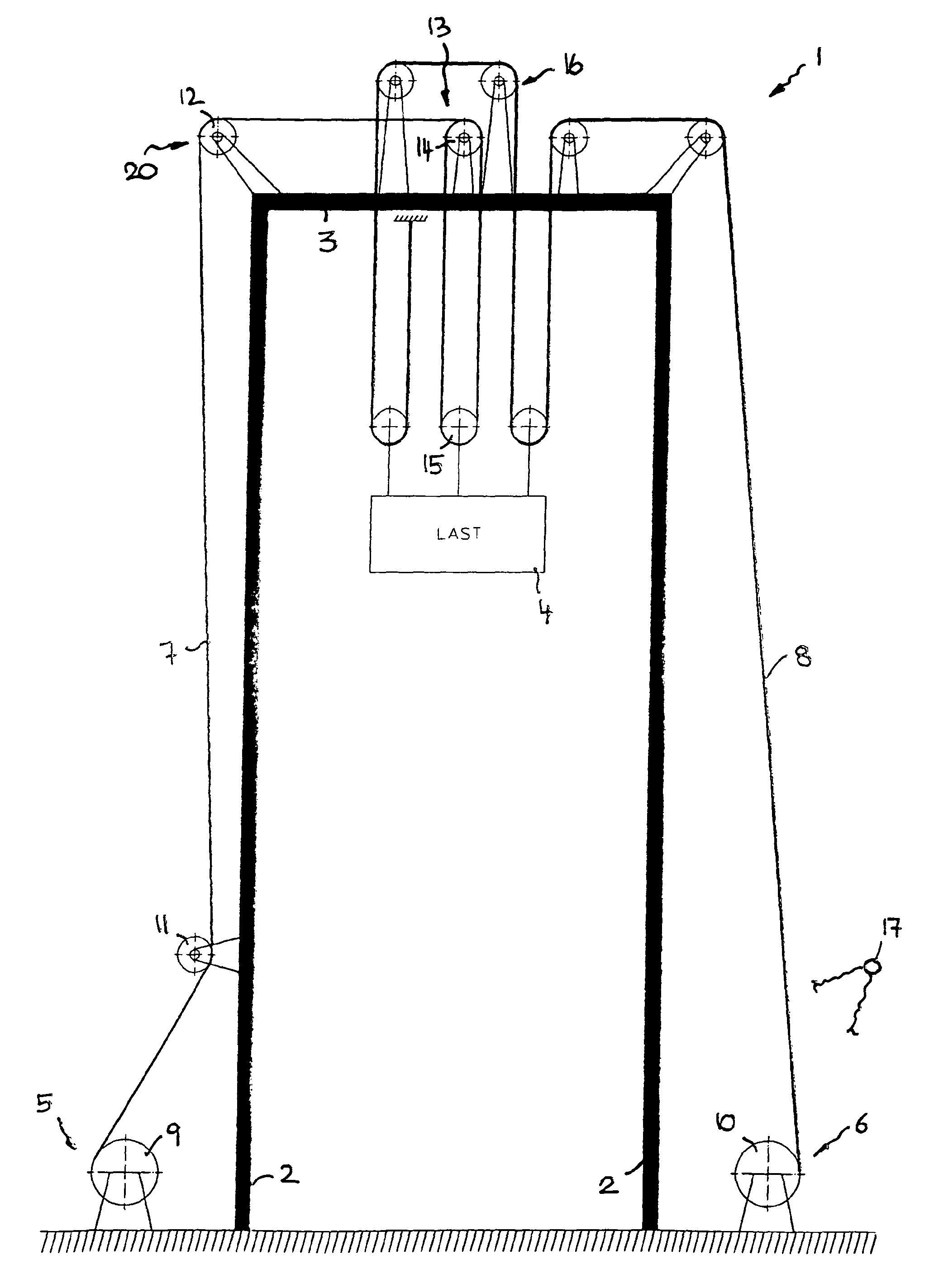
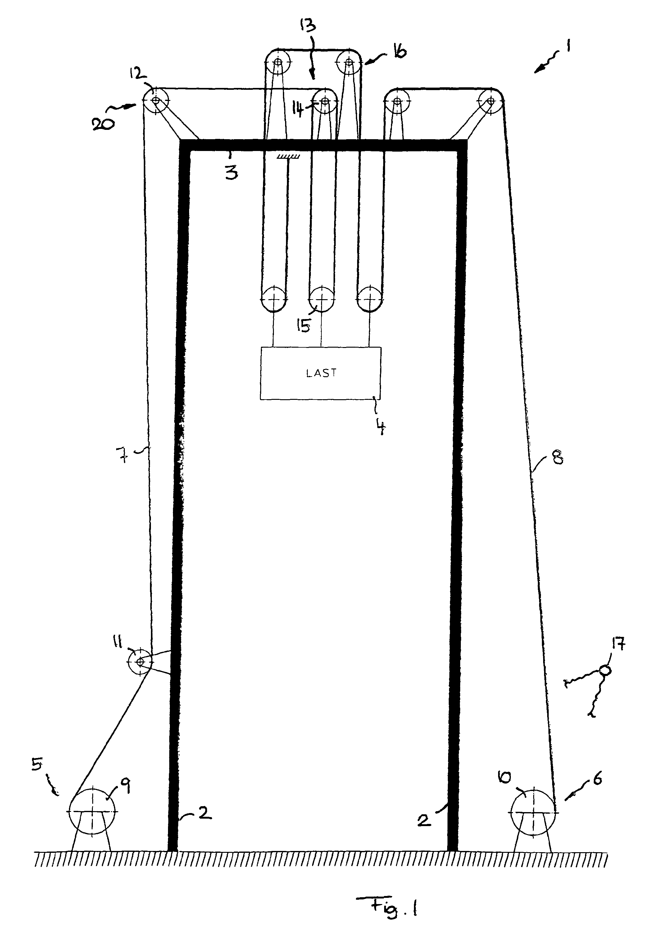
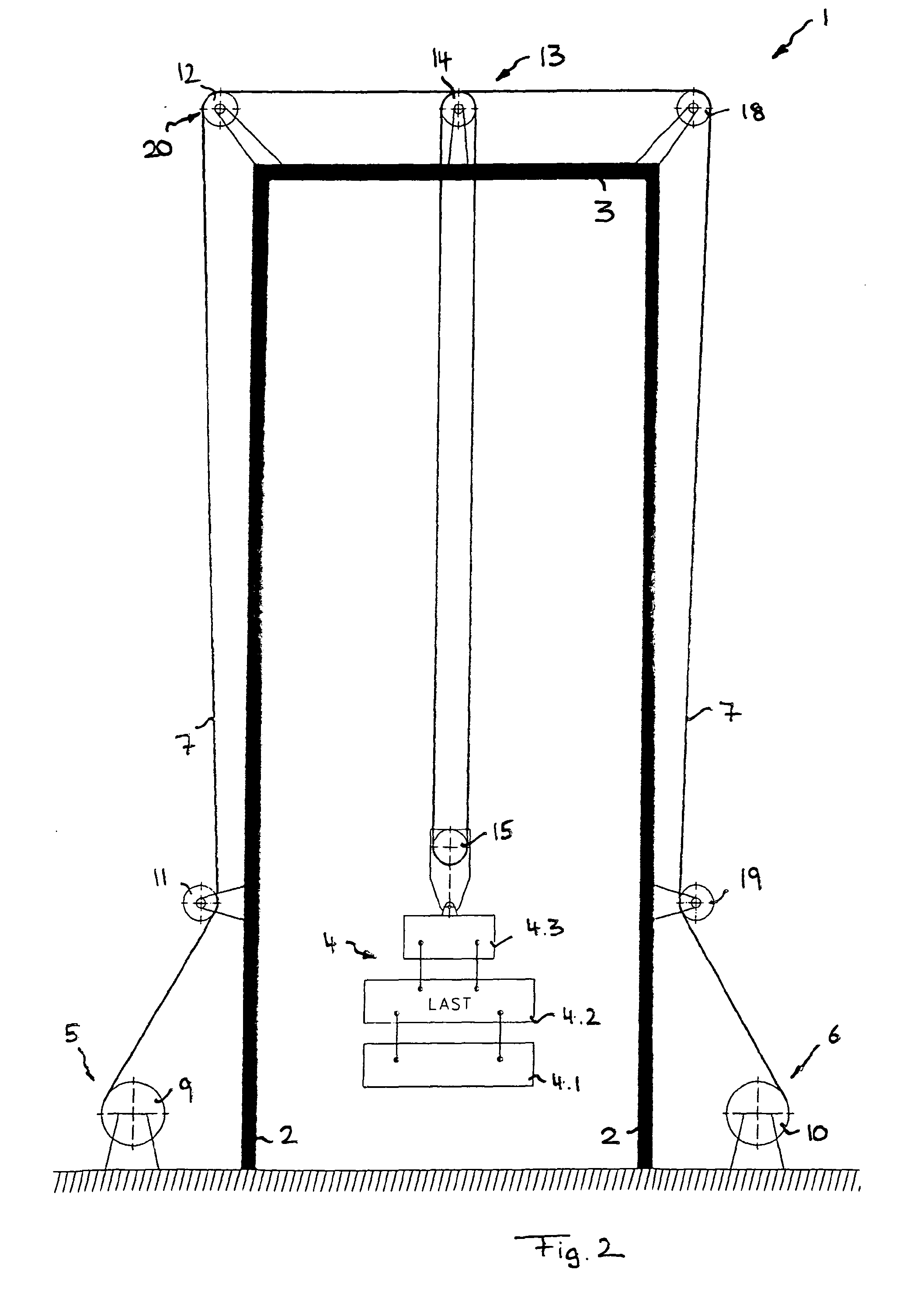
The patent describes a cable test stand that has two additional cable drives that can change the tension on the test cable without needing to change the load on it. This means that the amount of pressure applied to the cable can be adjusted for different parts, phases, or winding directions without having to modify the setup of the test stand. Additionally, the stand includes scanning means that can move with the cable movements to accurately determine the diameter of the cable, even if it is deflected. This allows for easier and more accurate testing of cables without needing to move the load on them.

Problems solved by technology

However, after a break of the cable, it is not easy to reset the test stand for further use, and sometimes requires a great deal of time.
A further disadvantage of cable test stands to date is that they only emulate the load cycles which occur in cranes and hoisting machines to a limited degree.
However, this does not correspond to the actual application of a cable in a cable drive system, for example in a lifting unit of hoisting machines.
These load cycles occurring in practice in cranes or other hoisting machines can only be insufficiently emulated by cable test stands used to date, because it is generally not possible to set down the load or pick up the load after the hoisting path has been traveled.
In addition, cable test stands to date only insufficiently determine the winding behavior of the cable as appropriate to actual practice.
In addition, such load cycles in the winding and unwinding of the cable also influence the life cycle of the cable, which cannot be sufficiently emulated by cable test benches to date.
It has also not been possible to reproduce this in test stands to date.

Method used


Image

  • Rope Test Stand
  • Rope Test Stand
  • Rope Test Stand

Examples


Embodiment Construction

[0052]To facilitate an understanding of the principles and features of the various embodiments of the invention, various illustrative embodiments are explained below. Although exemplary embodiments of the invention are explained in detail, it is to be understood that other embodiments are contemplated. Accordingly, it is not intended that the invention is limited in its scope to the details of construction and arrangement of components set forth in the following description or illustrated in the drawings. The invention is capable of other embodiments and of being practiced or carried out in various ways. Also, in describing the exemplary embodiments, specific terminology will be resorted to for the sake of clarity.

[0053]It must also be noted that, as used in the specification and the appended claims, the singular forms “a,”“an” and “the” include plural references unless the context clearly dictates otherwise. For example, reference to a component is intended also to include composit...


PUM


Abstract

A cable test bench for testing a test cable to establish service life, replacement age, number of flex cycles, and / or winding behavior, has a deflection system including at least one deflector roll to deflect the test cable, one test cable drive to wind and unwind the test cable via the deflection system, and one test load to load the test cable. The cable test stand has an additional cable test drive for winding and unwinding a safety cable and / or the named test cable, and a control device for controlling the additional cable drive and / or the test cable drive in a manner wherein the two are adjusted to each other, in such a manner that the load of the test cable can be adjusted differently for different test cable segments and / or different winding directions and / or different winding cycles and / or different phases of a winding cycle.

Description

CROSS-REFERENCE TO RELATED APPLICATIONS[0001]This application is a US National Stage of International Application No. PCT / EP2012 / 001795, filed 26 Apr. 2012, which claims the benefit of DE 10 2011 018 535.6, filed 26 Apr. 2011, both herein fully incorporated by reference.BACKGROUND OF THE INVENTION[0002]1. Field of the Invention[0003]The present invention relates to a cable test bench for testing a test cable to establish service life, replacement age, number of flex cycles, and / or winding behavior, having a deflection system comprising at least one deflector roll to deflect the test cable, one test cable drive to wind and unwind the test cable via the deflection system, and one test load to load the test cable.[0004]2. Description of Related Art[0005]Cables in safety applications, such as steel and fiber ropes of hoisting machines such as cranes, must be tested under test bench conditions to establish their service life, their replacement age, and their allowed number of flex cycles...

Claims


Application Information

Patent Timeline
IPC IPC(8): G01N3/32G01N3/08
CPCG01N3/08G01N3/32B66C15/00B66D1/54G01N2203/028
Inventor MUPDENDE, ILAKASTANGER, NORBERT
Owner LIEBHERR COMPONENTS BIBERACH GMBH
Learn More