Lighting structure and endoscope

Active Publication Date: 2014-04-17
THE FUJIKURA CABLE WORKS LTD
View PDF22 Cites 9 Cited by
  • Summary
  • Abstract
  • Description
  • Claims
  • Application Information

AI Technical Summary

Benefits of technology

The invention is a lighting structure that allows for a smaller optical observation device, like an endoscope, by transmitting the pumping light and image light through the same optical transmission medium. Additionally, the structure prevents halation and provides uniform illumination using a wavelength-selective reflective unit that directs the emitted fluorescing light in a different direction than the optical transmission medium, resulting in improved contrast.

Problems solved by technology

In the transmission of illuminating light using a fiber bundle and in view of a space in which the distal-end portion of the fiber bundle used for changing the illumination direction is bent or an optical component such as a prism or a conduit rod is provided, it is difficult to manufacture a small-diameter endoscope (particularly, used for observing an inner blood vessel or the like, the outer diameter thereof is 1 mm or less).
An increase in loss or wire breakage which is due to flexion of the fiber, or degradation in mechanical reliability may occur.
Furthermore, since the object distance is made short in the side-viewing endoscope, an illumination method or an illumination area is not sufficiently obtained or the range of vision cannot be sufficiently-illuminated; and since uniform illumination is difficult, halation or the like occurs, resulting in degradation in image quality.
In proposals that transmission of illuminating light and transmission of image are separately carried out as described in Japanese Unexamined Patent Application, First Publication No. 2010-160948 and Japanese Unexamined Patent Application, First Publication No. 2011-182871, the outer diameter increases, and it is difficult to manufacture a small-diameter endoscope.

Method used


Image

  • Lighting structure and endoscope
  • Lighting structure and endoscope
  • Lighting structure and endoscope

Examples


first embodiment

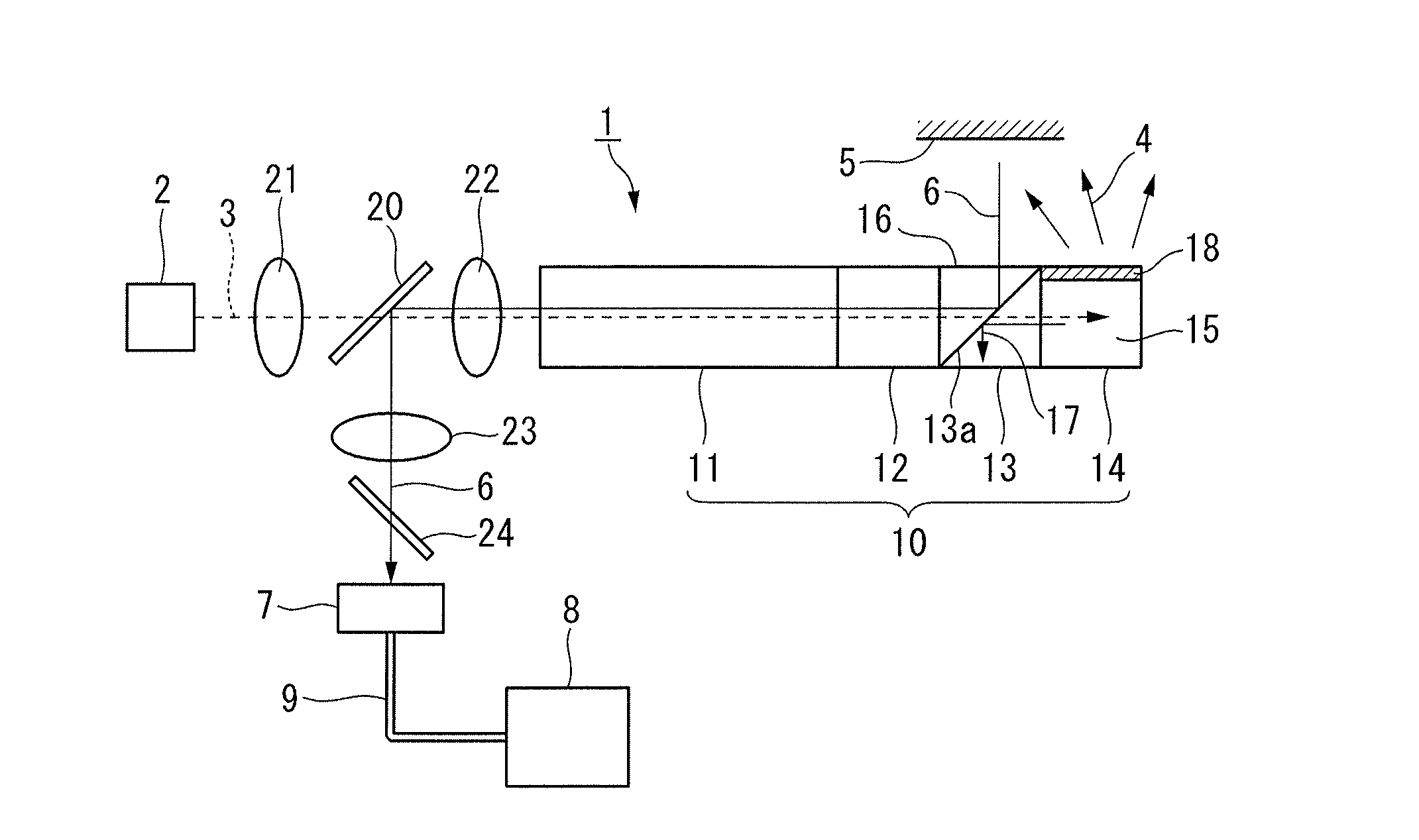
[0048]FIG. 1 shows a side-viewing endoscope 1 using a lighting structure 10 related to the invention.

[0049]The lighting structure 10 includes: an optical transmission medium 11 transmits pumping light 3 and image light 6 therethrough; an objective optical system 12 that is placed at the distal-end portion of the optical transmission medium 11; a wavelength conversion unit 14 including a fluorescent body 15 that receives the pumping light 3 transmitted through the optical transmission medium 11 and irradiates an object 5 with illuminating light 4; and a wavelength-selective reflective unit 13 including a wavelength filter 13a that selectively reflects a wavelength of the image light 6 and allows a wavelength of the pumping light 3 to selectively transmit therethrough.

[0050]The pumping light 3 is incident to the optical transmission medium 11 from a pumping light source 2, that is provided at the eyepiece side of the optical transmission medium 11 (left side in FIG. 1), and thereby tr...

second embodiment

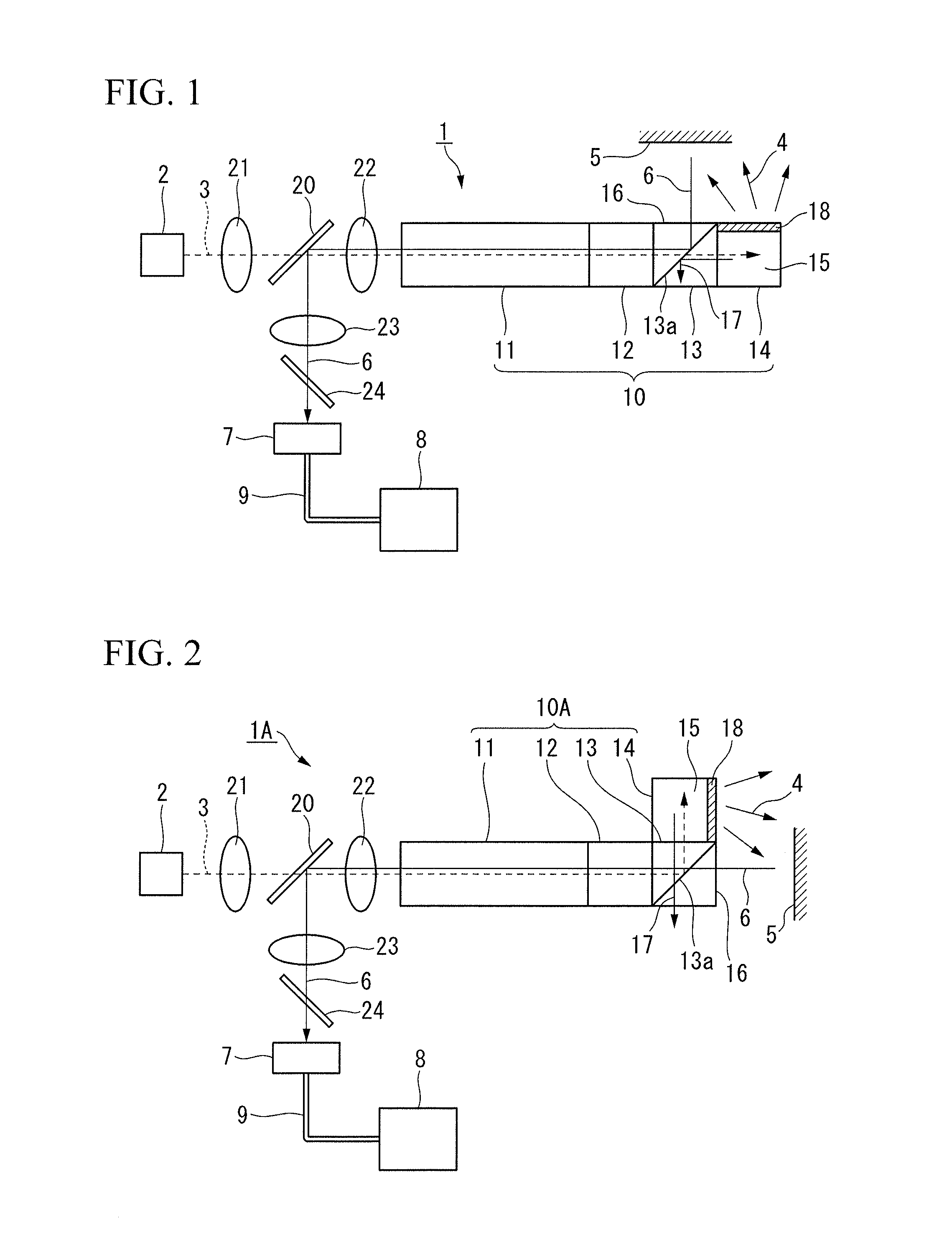
[0109]FIG. 2 shows a direct-view endoscope 1A using a lighting structure 10A related to the invention.

[0110]The lighting structure 10A includes: an optical transmission medium 11 transmits pumping light 3 and image light 6 therethrough; an objective optical system 12 that is placed at the distal-end portion of the optical transmission medium 11; a wavelength conversion unit 14 including a fluorescent body 15 that receives the pumping light 3 transmitted through the optical transmission medium 11 and irradiates an object 5 with illuminating light 4; and a wavelength-selective reflective unit 13 including a wavelength filter 13a that selectively reflects a wavelength of the pumping light 3 and allows a wavelength of the image light 6 to selectively transmit therethrough.

[0111]In terms of difference in the characteristics of the wavelength filter 13a in addition to in the terms of the objective part 16 that faces the object 5 and is provided on an extension line in the longitudinal dir...


PUM


Abstract

A lighting structure includes: an optical transmission medium that transmits pumping light and image light; an objective optical system that is disposed at a distal-end portion of the optical transmission medium; a wavelength conversion unit comprising a fluorescent body that receives the pumping light transmitted through the optical transmission medium and irradiates an object with illuminating light; and a wavelength-selective reflective unit that selectively reflects one of a wavelength of the pumping light and a wavelength of the image light, thereby emits pumping light that is incident thereto through the optical transmission medium into the fluorescent body and emits image light that is incident from the object into the optical transmission medium through the objective optical system.

Description

CROSS REFERENCE TO RELATED APPLICATIONS[0001]This application is a continuation application based on a PCT Patent Application No. PCT / JP2013 / 062604, filed Apr. 30, 2013, whose priority is claimed on Japanese Patent Application No. 2012-130858 filed on Jun. 8, 2012, the content of which is hereby incorporated by reference.BACKGROUND OF THE INVENTION[0002]The present invention relates to a lighting structure used for an optical observation device such as an endoscope, and an endoscope using the same.DESCRIPTION OF THE RELATED ART[0003]Conventionally, a side-viewing endoscope transmits illuminating light to a distal end of the endoscope through a bundle (fiber bundle) of an optical fiber that transmits the illuminating light (a multi-component glass fiber having approximately 30 to 50 μm is commonly used), changes the illumination direction of the illuminating light emitted from the end of the optical fiber into a viewing field direction, performs light guiding, and emits the light.[00...

Claims


Application Information

Patent Timeline
IPC IPC(8): A61B1/06A61B1/00A61B1/313A61B1/07
CPCA61B1/0653A61B1/0661A61B1/3137A61B1/00096A61B1/0646A61B1/07A61B1/00165A61B1/00177A61B1/00186G02B23/2461G02B23/2469G02B23/26
Inventor NAKATATE, KENICHIIIKURA, HITOE
Owner THE FUJIKURA CABLE WORKS LTD
Why Eureka
Try Eureka