
Imaging surface modeling for camera modeling and virtual view synthesis

a camera model and image technology, applied in the field of image capture and processing of invehicle vision systems, can solve the problems of only having a limited distortion correction feature, image distortion around the edges of the image, and becoming unusable or inaccurate for the person viewing the reproduced image, so as to enhance the region or direction of the vehicle, enhance the center portion of the captured image, enhance the effect of the region or direction the vehicle is turning

Active Publication Date: 2014-04-17
GM GLOBAL TECH OPERATIONS LLC
View PDF24 Cites 92 Cited by
  • Summary
  • Abstract
  • Description
  • Claims
  • Application Information

AI Technical Summary

Benefits of technology

The invention described in this patent allows for the creation of virtual images using real cameras and various image effects. This includes generating images from different camera positions and utilizing non-planar surfaces to enhance specific parts of the image. The virtual camera model with non-planar imaging surface is mapped to the captured real image and projected onto a display device for viewing. The technique uses a non-planar imaging surface for modeling the captured image in a virtual camera model, which improves the quality of the virtual image. The invention allows for better enhancement of different regions of the captured image and better adjustment to operating conditions of the vehicle, resulting in a more realistic and accurate virtual image.

Problems solved by technology

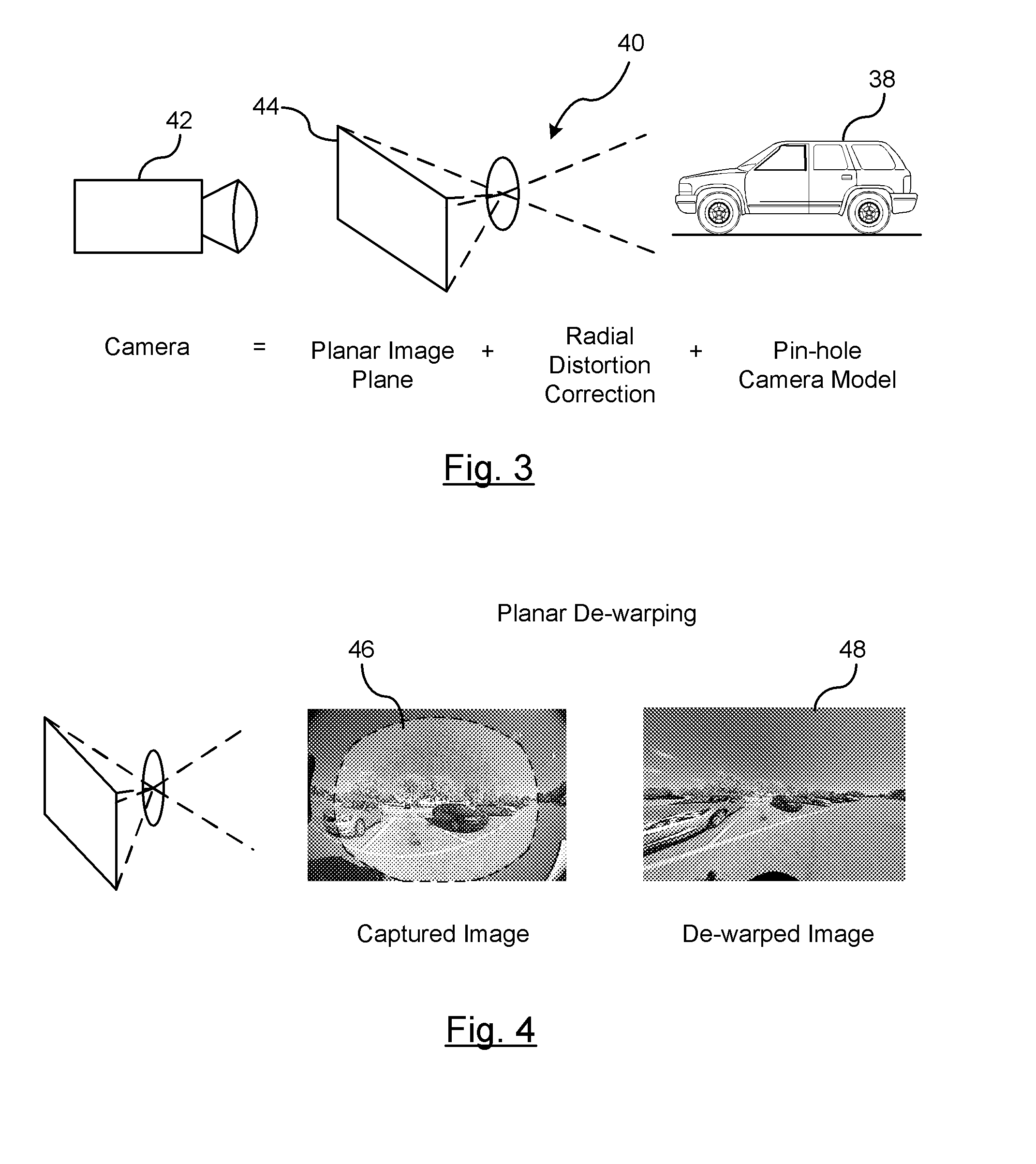
Camera modeling which takes a captured input image from a device and remodels the image to show or enhance a respective region of the captured image must reorient all objects within the image without distorting the image so much that it becomes unusable or inaccurate to the person viewing the reproduced image.
Wide FOV cameras typically provide curved images that cause image distortion around the edges of the image.
Traditional virtual camera modeling uses a planar imaging surface representing the flat image sensor within a camera; however, such systems can only do limited distortion correction feature when projected on to a display device.

Method used


Image

  • Imaging surface modeling for camera modeling and virtual view synthesis
  • Imaging surface modeling for camera modeling and virtual view synthesis
  • Imaging surface modeling for camera modeling and virtual view synthesis

Examples


Embodiment Construction

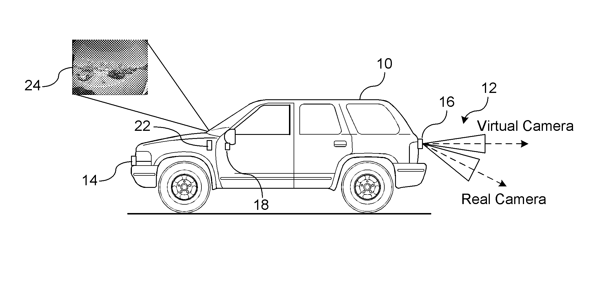
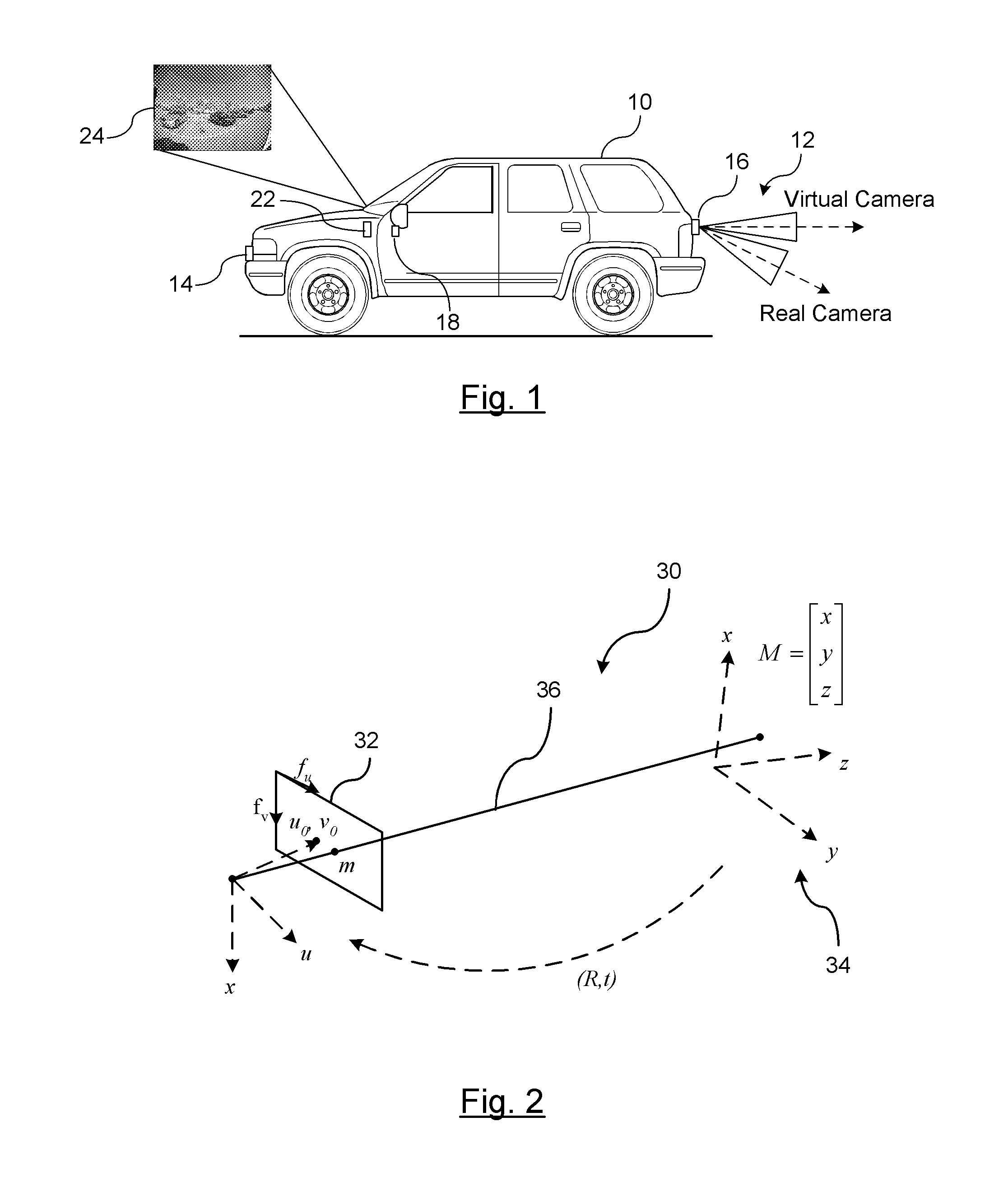
[0027]There is shown in FIG. 1, a vehicle 10 traveling along a road. A vision-based imaging system 12 captures images of the road. The vision-based imaging system 12 captures images surrounding the vehicle based on the location of one or more vision-based capture devices. In the embodiments described herein, the vision-based imaging system will be described as capturing images rearward of the vehicle; however, it should also be understood that the vision-based imaging system 12 can be extended to capturing images forward of the vehicle and to the sides of the vehicle.

[0028]The vision-based imaging system 12 includes a front-view camera 14, a rear-view camera 16, a left-side view camera 18, and a right-side view camera (not shown). The cameras 14-18 can be any camera suitable for the purposes described herein, many of which are known in the automotive art, that are capable of receiving light, or other radiation, and converting the light energy to electrical signals in a pixel format ...


PUM


Abstract

A method for displaying a captured image on a display device. A real image is captured by a vision-based imaging device. A virtual image is generated from the captured real image based on a mapping by a processor. The mapping utilizes a virtual camera model with a non-planar imaging surface. Projecting the virtual image formed on the non-planar image surface of the virtual camera model to the display device.

Description

CROSS-REFERENCE TO RELATED APPLICATIONS[0001]This application claims priority of U.S. Provisional Application Ser. No. 61 / 712,433 filed Oct. 11, 2012, the disclosure of which is incorporated by reference.BACKGROUND OF INVENTION[0002]An embodiment relates generally to image capture and processing for in-vehicle vision systems.[0003]Vehicle systems often use in-vehicle vision systems for rear-view scene detections, side-view scene detection, and forward view scene detection. For those applications that require graphic overlay or to emphasize an area of the captured image, it is critical to accurately calibrate the position and orientation of the camera with respect to the vehicle and the surrounding objects. Camera modeling which takes a captured input image from a device and remodels the image to show or enhance a respective region of the captured image must reorient all objects within the image without distorting the image so much that it becomes unusable or inaccurate to the person...

Claims


Application Information

Patent Timeline
IPC IPC(8): H04N7/18
CPCH04N7/18B60R2300/306G06T7/75G06T3/12B60R1/27B60R1/28H04N23/698G06T3/047B60R2300/10B60R2300/802B60R2300/8093G06T2207/30244G06T2207/30264
Inventor ZHANG, WENDEWANG, JINSONGLITKOUHI, BAKHTIAR BRIANLYBECKER, KENT S.FRAKES, RYAN M.
Owner GM GLOBAL TECH OPERATIONS LLC
Learn More