
Cooling apparatus for internal combustion engine

Active Publication Date: 2014-04-17
TOYOTA JIDOSHA KK
View PDF1 Cites 2 Cited by
  • Summary
  • Abstract
  • Description
  • Claims
  • Application Information

AI Technical Summary

Benefits of technology

The invention is a cooling system for internal combustion engines that reduces knocking, prevents energy loss, and minimizes noise and cooling temperature variations caused by the fan. It achieves this by controlling the fan based on vehicle speed, and using two different driving voltages to improve cooling performance. The system also includes a fan stop threshold to prevent hunting during fan operation. Overall, the system prevents knocking, improves fuel efficiency, and reduces cooling temperature variations, making it ideal for use in automobiles.

Problems solved by technology

When such coolant temperature control is used as a measure for improving the fuel efficiency, it may possibly induce problems as follows.
This may result in increased coolant temperature.
If the vehicle is rapidly accelerated after the increase of the coolant temperature, knocking may likely occur due to the ignition timing that is adjusted according to the coolant temperature set lower than normal.
When the retardation amount at a low coolant temperature is increased by the learning function, it may possibly induce deterioration of fuel efficiency performance, or deficiency in motivity performance such as slow acceleration.
According to this technique, in which control is performed with reference to the coolant temperature, the coolant temperature might be increased at some timing due to delayed response of the coolant temperature control, making it impossible to prevent occurrence of knocking.
In addition, if the fan is activated frequently in order to keep the coolant in a low temperature state as much as possible, the fuel efficiency might be rather deteriorated due to increased power consumption by the fan or increased driving resistance.
Furthermore, the frequent activation of the fan may possibly cause a problem of activation noise or increase of variation range of the coolant temperature.
Still further, frequent activation of the fan will reduce the lifetime of the fan itself.

Method used


Image

  • Cooling apparatus for internal combustion engine
  • Cooling apparatus for internal combustion engine
  • Cooling apparatus for internal combustion engine

Examples


Embodiment Construction

[0023]An embodiment of the invention will be described with reference to the accompanying drawings. It should be noted that, in the drawings, dimensions and proportions of components do not necessarily reflect the actual dimensions and proportions.

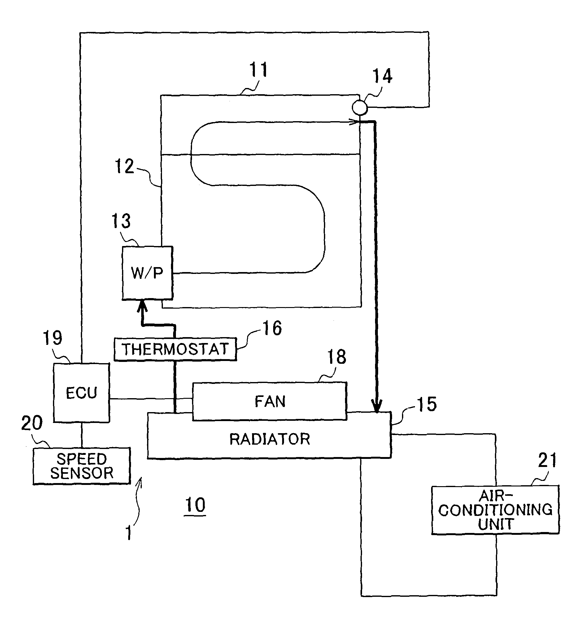
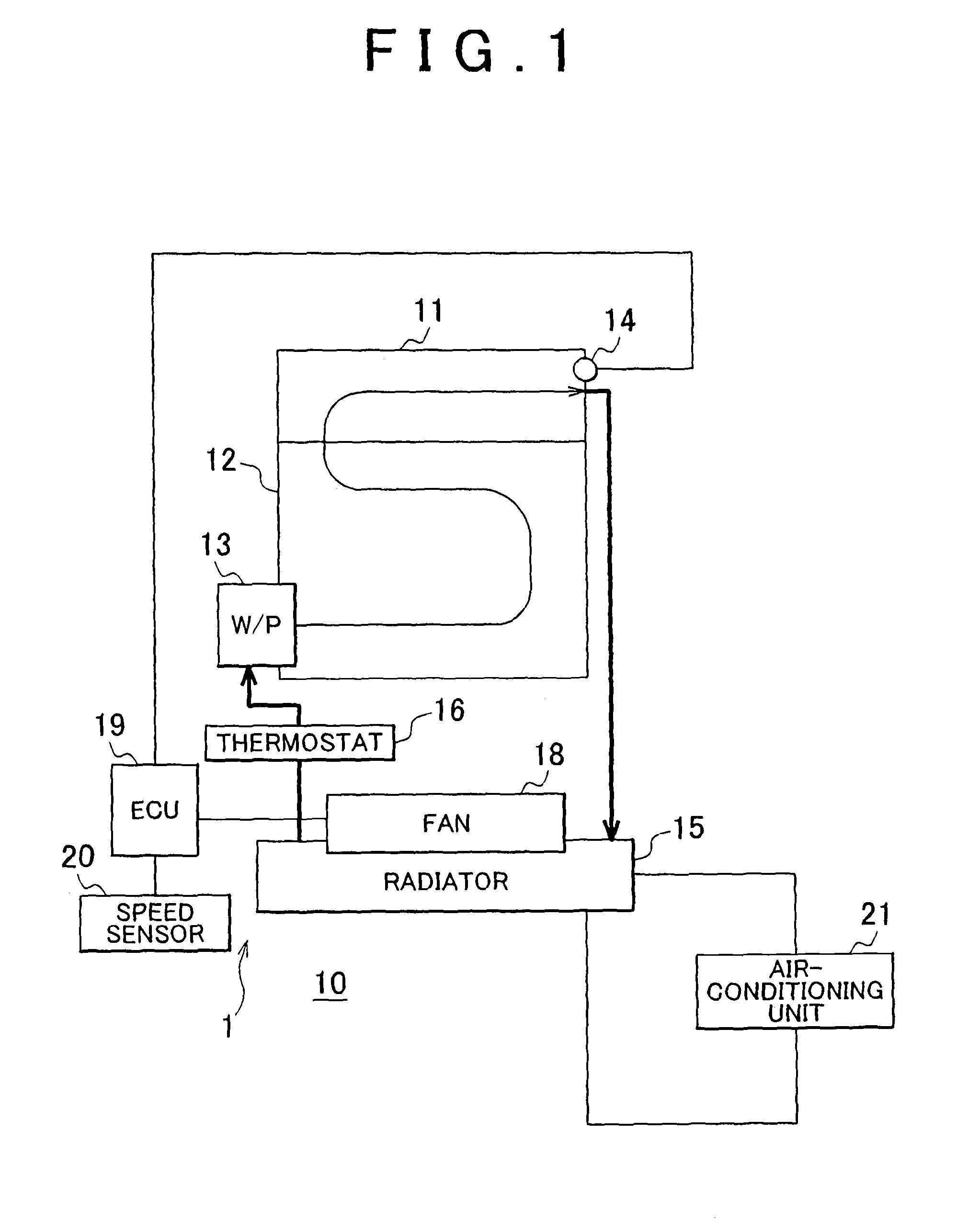
[0024]Referring to FIG. 1, a description will be made of a schematic configuration of an internal combustion engine 10 in which a cooling apparatus 1 for internal combustion engine (hereafter, simply referred to as the “cooling apparatus”) according to an embodiment of the invention is incorporated. The internal combustion engine 10 has a cylinder head 11 and a cylinder block 12. A water pump (W / P) 13 is provided on a side of the cylinder block 12. A water jacket is provided in each of the cylinder head 11 and the cylinder block 12. A coolant fed under pressure by the water pump 13 flows through the cylinder block 12 and the cylinder head 11 in this order, and is once discharged to the outside from the cylinder head 11. A temperature senso...


PUM


Abstract

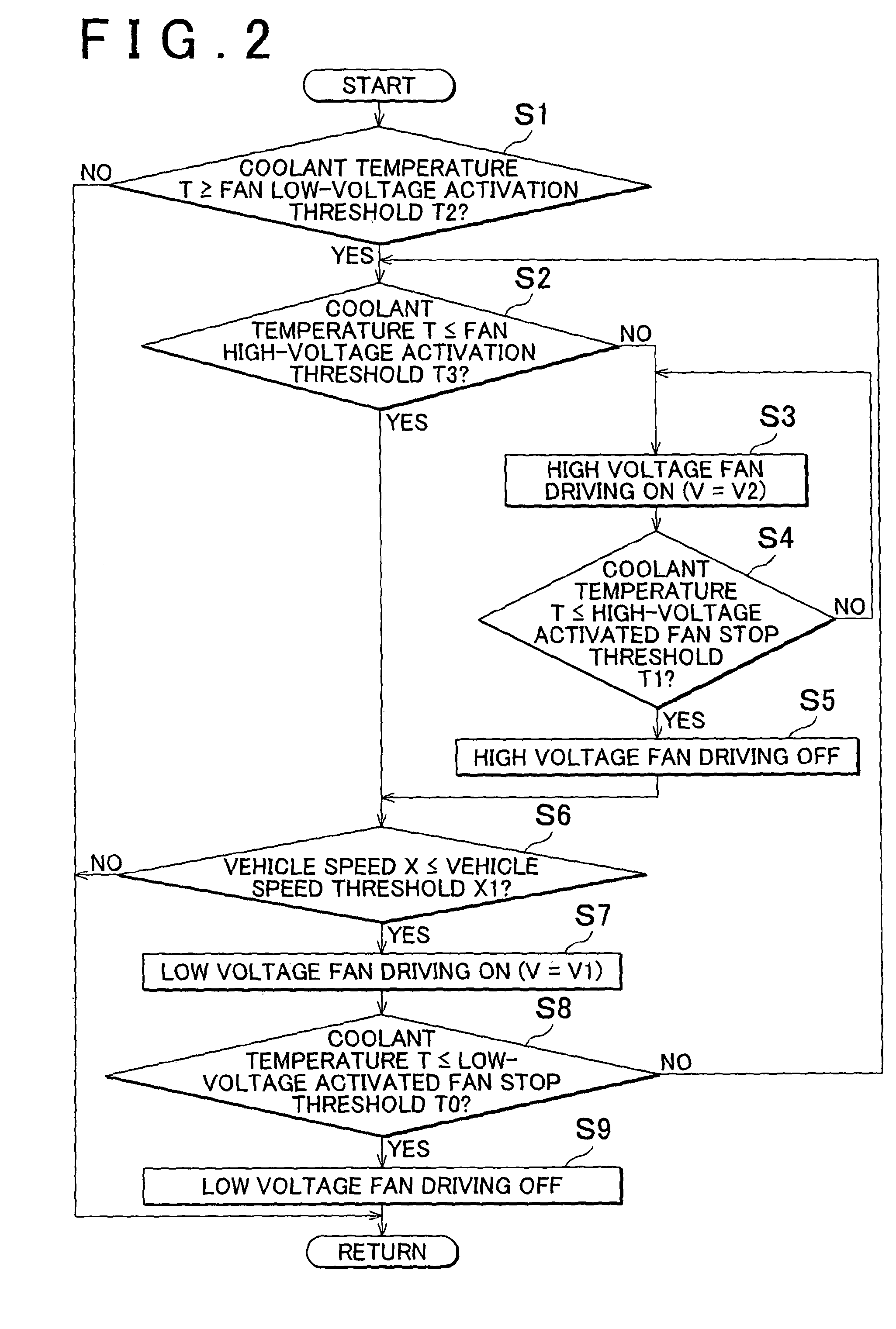
A cooling apparatus for an internal combustion engine includes a fan that cools a coolant by operating at least at a first drive voltage and a second drive voltage higher than the first drive voltage; and a control unit that drives the fan at the first drive voltage when a vehicle is driven at a low vehicle speed that is a vehicle speed lower than a vehicle speed threshold and a coolant temperature is higher than a fan low-voltage activation threshold.

Description

BACKGROUND OF THE INVENTION[0001]1. Field of the Invention[0002]This invention relates to a cooling apparatus for use in internal combustion engines.[0003]2. Description of Related Art[0004]Various proposals have been made regarding control of coolant temperature in internal combustion engines. For example, Japanese Patent Application Publication No. 60-81422 (JP 60-81422 A) discloses a control mechanism for an automobile electric-powered fan, which is designed to increase the rotational speed of the electric-powered fan with increase in coolant temperature.[0005]In the meantime, there has recently been proposed to control the coolant temperature for the purpose of improving the fuel efficiency by suppressing knocking. Specifically, in order to suppress knocking, the coolant temperature is controlled to be lower than a common coolant temperature to suppress knocking so that the fuel efficiency is improved. When the coolant temperature is normally set lower in this manner, the igniti...

Claims


Application Information

Patent Timeline
IPC IPC(8): G05B11/18
CPCG05B11/18F01P7/048F01P7/08F01P2025/66
Inventor KAWAMOTO, NOBUKIHASHIMOTO, YASUKIYAMAMOTO, HIROSHI
Owner TOYOTA JIDOSHA KK
Learn More