
Feed line switching apparatus, optical submarine branching apparatus, submarine cable system, and feed line switching method

a technology of submarine branching and switching apparatus, which is applied in the direction of line-transmission details, power feeding arrangements, manufacturing tools, etc., can solve the problem of difficult control of feed lines

Active Publication Date: 2014-04-17
NEC CORP
View PDF1 Cites 17 Cited by
  • Summary
  • Abstract
  • Description
  • Claims
  • Application Information

AI Technical Summary

Benefits of technology

The patent text is describing a new invention that allows for more efficient and accurate printing onto a small surface. The invention uses a special printing technology that overcomes limitations associated with traditional printing methods, resulting in a higher quality and more precise print. Overall, the patent describes a way to improve printing accuracy and quality on small surfaces.

Problems solved by technology

As the network becomes complex, control of the feed lines becomes difficult in a current-switching type branching apparatus and thus a remote control type submarine branching apparatus is used.

Method used


Image

  • Feed line switching apparatus, optical submarine branching apparatus, submarine cable system, and feed line switching method
  • Feed line switching apparatus, optical submarine branching apparatus, submarine cable system, and feed line switching method
  • Feed line switching apparatus, optical submarine branching apparatus, submarine cable system, and feed line switching method

Examples


Embodiment Construction

[0026]Hereinafter, exemplary embodiments of the present invention will be described with reference to drawings.

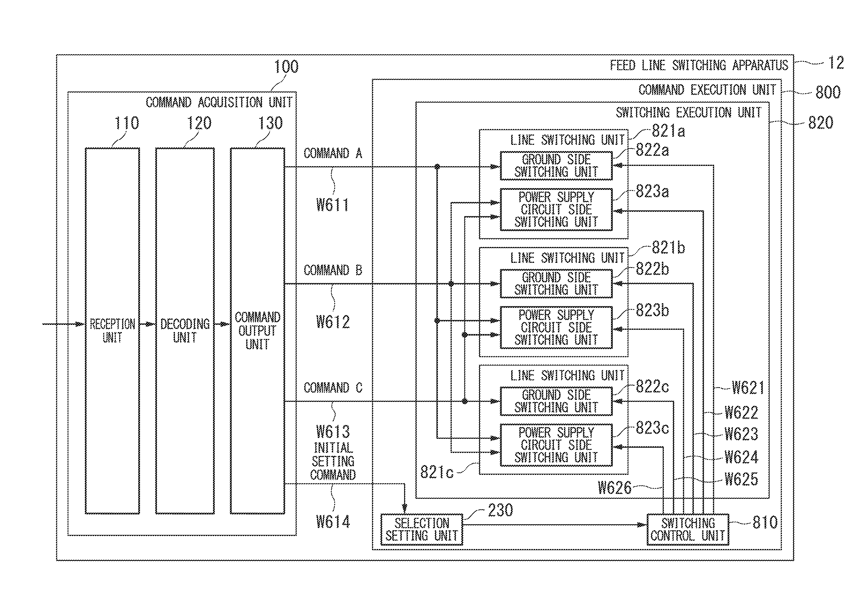
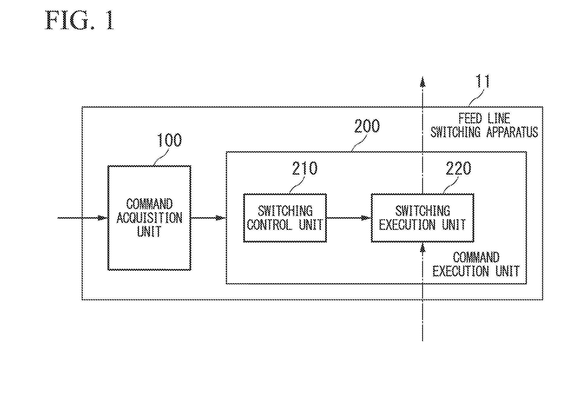
[0027]FIG. 1 is a configuration diagram illustrating a schematic configuration of a feed line switching apparatus in an exemplary embodiment of the present invention. In FIG. 1, a feed line switching apparatus 11 includes a command acquisition unit 100 and a command execution unit 200. The command execution unit 200 includes a switching control unit 210 and a switching execution unit 220.

[0028]The feed line switching apparatus 11 switches a connection relationship of a plurality of feed lines. The feed line referred to herein is an individual power supply cable connected to the feed line switching apparatus 11 (a power reception terminal included in the switching execution unit 220). It is to be noted that hereinafter, switching of the connection relationship of the feed lines is referred to as “feed line switching”.

[0029]The command acquisition unit 100 acquires a feed lin...


PUM

PropertyMeasurementUnit
Poweraaaaaaaaaa

Abstract

In a feed line switching apparatus, a situation in which the feed line switching apparatus cannot work when feed lines have a predetermined connection relationship is prevented. The feed line switching apparatus includes a command acquisition unit which acquires a feed line switching command which designates a connection relationship of feed lines, a switching execution unit which switches the connection relationship of the feed lines in accordance with the feed line switching command acquired by the command acquisition unit, and a switching control unit which suppresses switching of the connection relationship of the feed lines in the switching execution unit for a predetermined feed line switching command.

Description

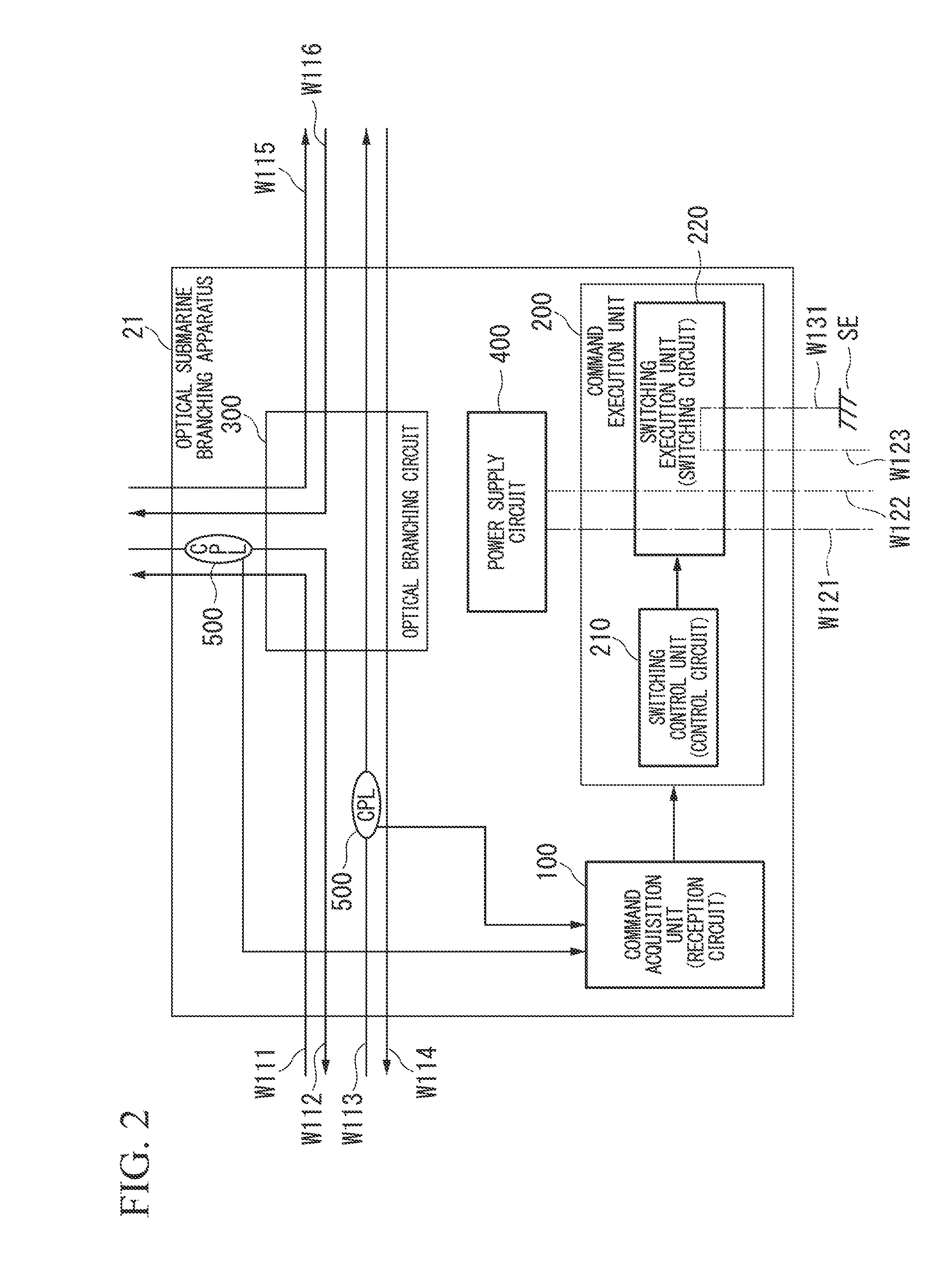
TECHNICAL FIELD[0001]The present invention relates to a feed line switching apparatus, an optical submarine branching apparatus, a submarine cable system, and a feed line switching method.BACKGROUND ART[0002]A feed line switching apparatus or a feed line switching circuit which switches a connection relationship of a plurality of feed lines is used in, for example, an optical submarine branching apparatus used in a submarine cable system, and, when failure occurs in a feed line to the optical submarine branching apparatus, performs switching to another feed line.[0003]For example, the optical submarine branching apparatus which switches a feed line in accordance with a command signal is called a remote control type submarine branching apparatus. Here, in the submarine cable system, building of a network including a plurality of branching apparatuses and terminal station apparatuses is required because of a request for a growing mesh of the network, reduction of construction cost, or...

Claims


Application Information

Patent Timeline
IPC IPC(8): H02J4/00
CPCH02J4/00H04B3/44H04B10/25H04B10/808
Inventor TAKIGAWA, YOSHINARI
Owner NEC CORP
Learn More