
Extremity imaging apparatus for cone beam computed tomography

a computed tomography and extremity imaging technology, applied in the field of diagnostic imaging, can solve the problems of difficult to obtain cbct, hampered cbct imaging of legs, arms, other extremities, etc., and achieve the effect of achieving a much more than about 180 degree revolution for knee or other imaging

Active Publication Date: 2014-04-10
CARESTREAM HEALTH INC
View PDF7 Cites 27 Cited by
  • Summary
  • Abstract
  • Description
  • Claims
  • Application Information

AI Technical Summary

Benefits of technology

The patent text describes an application that provides apparatus and method embodiments that can adapt to different imaging conditions and allow patients to be in various positions for suitable imaging of extreme parts of the body. Additionally, the patent text also mentions the use of a door-like structure to close gaps in a scanner to increase the space within the scan volume.

Problems solved by technology

Although 3-D images of diagnostic quality can be generated using CBCT systems and technology, a number of technical challenges remain.
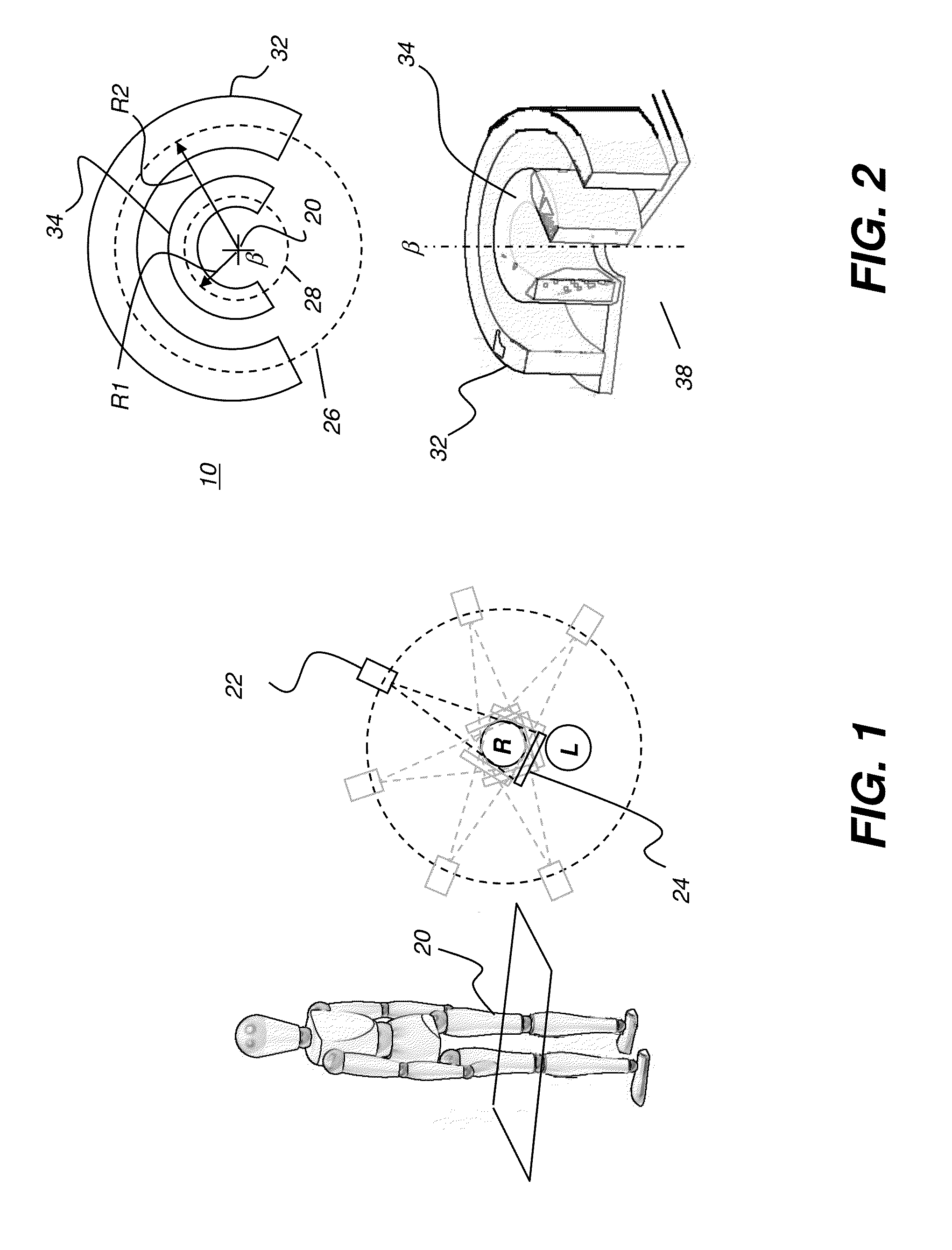
CBCT Imaging of legs, arms, and other extremities can be hampered by physical obstruction from a paired extremity.
This is an obstacle that is encountered in obtaining CBCT image projections for the human leg or knee, for example.
Not all imaging positions around the knee are accessible; the patient's own anatomy often prevents the radiation source and image detector from being positioned over a portion of the scan circumference.
However, in some cases it can be difficult to obtain much more than about 180 degree revolution for imaging the knee or other joints and other applications.
But, if the patient is required to assume a position that is not usually encountered in typical movement or posture, there may be excessive strain, or insufficient strain, or poorly directed strain or tension, on the joint.
Images of extremities under these conditions may fail to accurately represent how an extremity or joint is used and may not provide sufficient information for assessment and treatment planning.
Still other difficulties with conventional solutions for extremity imaging relate to poor image quality.
Positioning the subject midway between the detector and the source, as some conventional systems have done, not only noticeably compromises image quality, but also places the patient too near the radiation source, so that radiation levels are considerably higher.
CBCT imaging represents a number of challenges that also affect other types of volume imaging that employ a radiation source and detector orbiting an extremity over a range of angles.

Method used


Image

  • Extremity imaging apparatus for cone beam computed tomography
  • Extremity imaging apparatus for cone beam computed tomography
  • Extremity imaging apparatus for cone beam computed tomography

Examples


Embodiment Construction

[0074]The following is a description of exemplary embodiments of the invention, examples of which are illustrated in the accompanying drawings. Wherever possible, the same reference numbers will be used throughout the drawings to refer to the same or like parts.

[0075]For illustrative purposes, principles of the invention are described herein by referring mainly to exemplary embodiments thereof. However, one of ordinary skill in the art would readily recognize that the same principles are equally applicable to, and can be implemented in, all types of radiographic imaging arrays, various types of radiographic imaging apparatus and / or methods for using the same and that any such variations do not depart from the true spirit and scope of the application. Moreover, in the following description, references are made to the accompanying figures, which illustrate specific exemplary embodiments. Electrical, mechanical, logical and structural changes can be made to the embodiments without depa...


PUM


Abstract

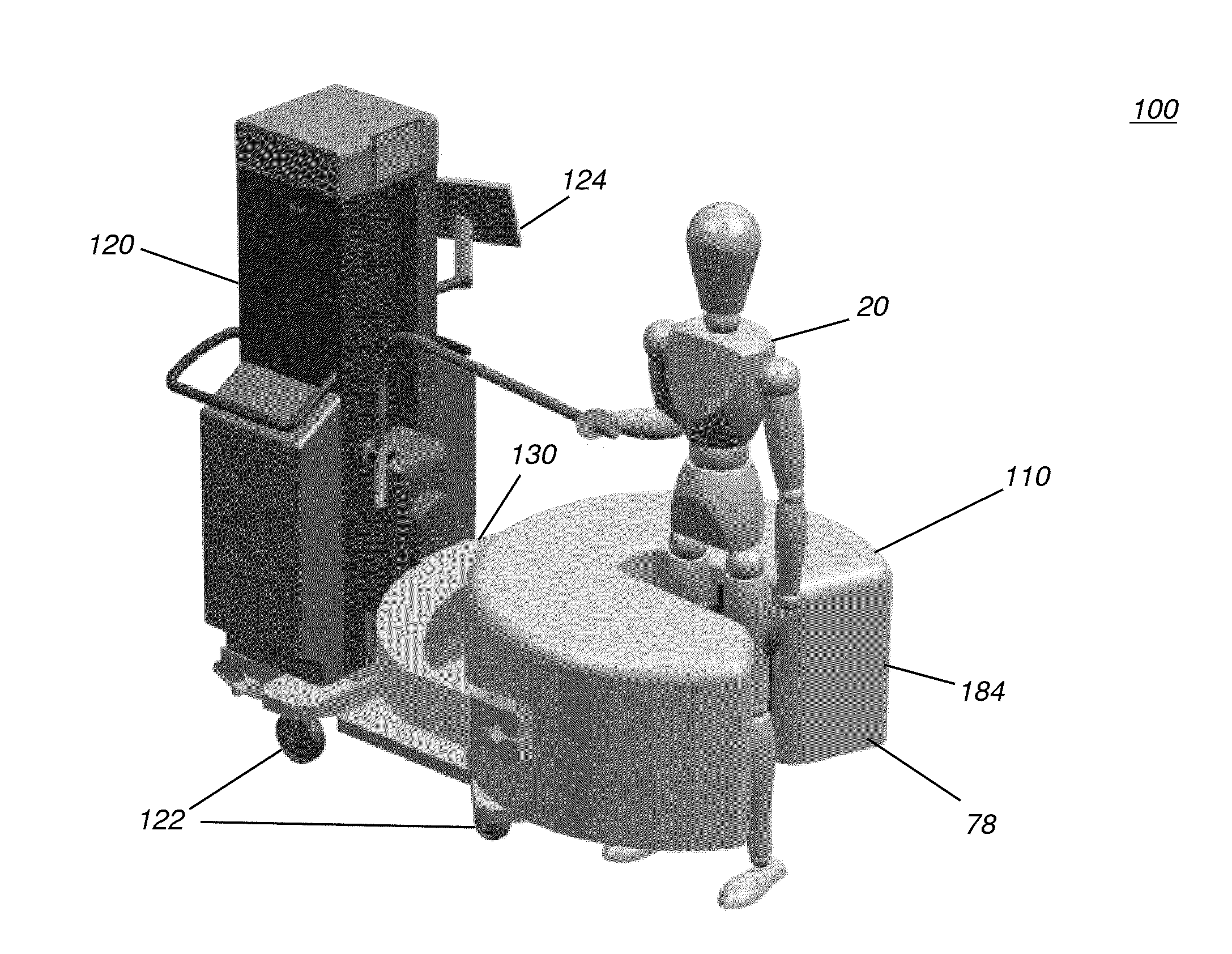
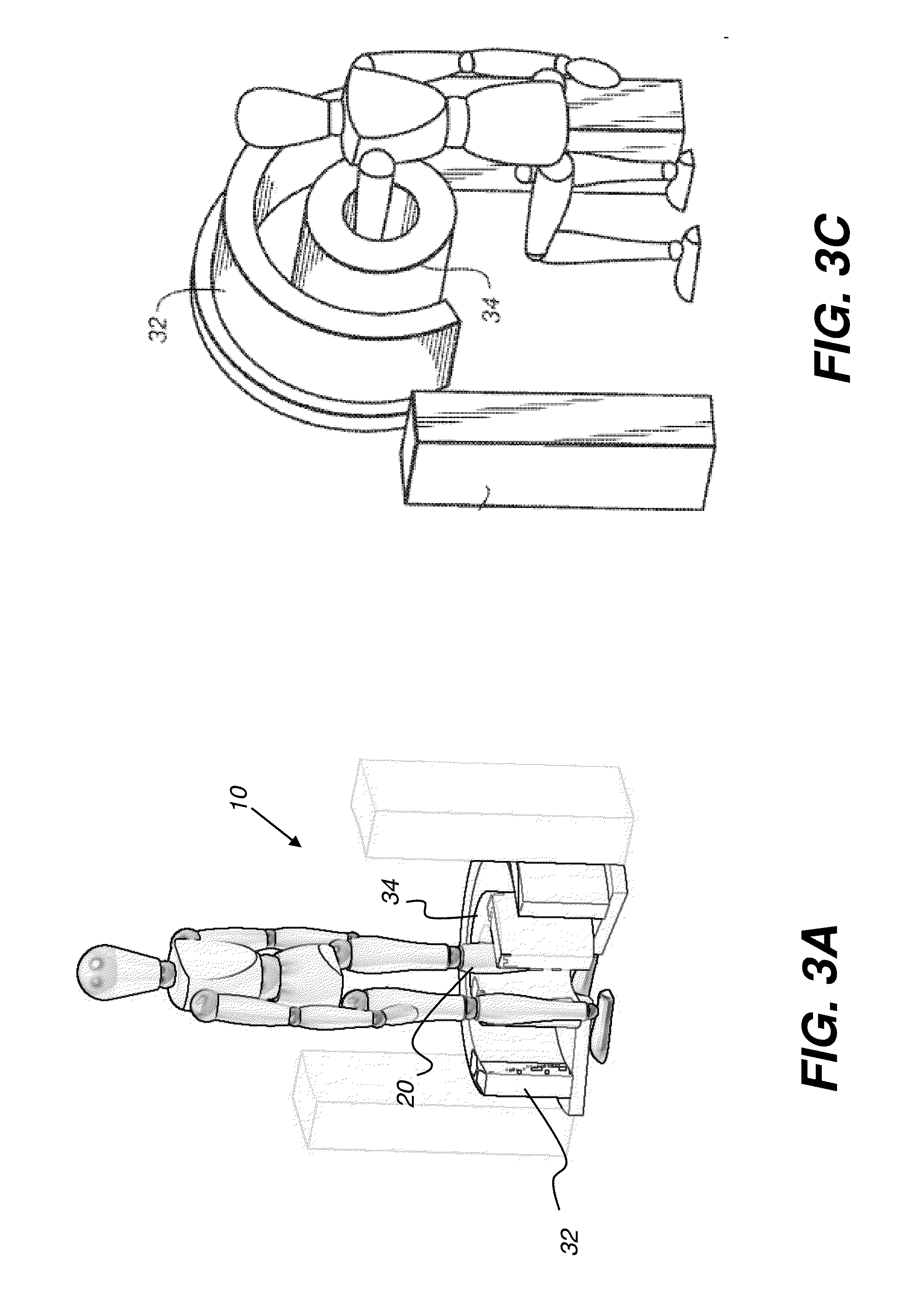
An apparatus for cone beam computed tomography can include a support structure, a scanner assembly coupled to the support structure for controlled movement in at least x, y and z orientations, the scanner assembly can include a DR detector configured to move along at least a portion of a detector path that extends at least partially around a scan volume with a distance D1 that is sufficiently long to allow the scan volume to be positioned within the detector path; a radiation source configured to move along at least a portion of a source path outside the detector path, the source path having a distance D2 greater than the distance D1, the distance D2 being sufficiently long to allow adequate radiation exposure of the scan volume for an image capture by the detector; and a first gap in the detector path.

Description

CROSS REFERENCE TO RELATED APPLICATIONS[0001]This application claims the benefit of U.S. Provisional application U.S. Ser. No. 61 / 710,832, provisionally filed on Oct. 8, 2012, entitled “EXTREMITY SCANNER AND METHODS FOR USING THE SAME”, in the names of John Yorkston et al., which is incorporated herein by reference in its entirety.FIELD OF THE INVENTION[0002]The invention relates generally to diagnostic imaging and in particular to cone beam imaging systems used for obtaining volume images of extremities.BACKGROUND OF THE INVENTION[0003]3-D volume imaging has proved to be a valuable diagnostic tool that offers significant advantages over earlier 2-D radiographic imaging techniques for evaluating the condition of internal structures and organs. 3-D imaging of a patient or other subject has been made possible by a number of advancements, including the development of high-speed imaging detectors, such as digital radiography (DR) detectors that enable multiple images to be taken in rapi...

Claims


Application Information

Patent Timeline
IPC IPC(8): A61B6/00
CPCA61B6/50A61B6/025A61B6/4085A61B6/4233A61B6/4405A61B6/4429A61B6/4447A61B6/4452A61B6/4482A61B6/461A61B6/467A61B6/527A61B6/541A61B6/548A61B6/0492F04C2270/041A61B6/032A61B6/035A61B6/4441A61B6/04
Inventor LITZENBERGER, MICHAEL A.STAGNITTO, JOSEPH E.DIRISIO, ANTHONYNEWMAN, PETER A.WENDLANDT, WILLIAM C.
Owner CARESTREAM HEALTH INC
Learn More