
Opening and closing module, control method for the same, imaging apparatus using the same

a control method and module technology, applied in the field of opening and closing modules, can solve the problems of increasing the space occupied by the imaging apparatus, vibration may occur, etc., and achieve the effect of reducing vibration during rotation and being easy to s

Active Publication Date: 2011-12-29
KOREA INST OF IND TECH
View PDF1 Cites 22 Cited by
  • Summary
  • Abstract
  • Description
  • Claims
  • Application Information

AI Technical Summary

Benefits of technology

[0009]The present invention has been made in an effort to provide an imaging apparatus in which vibration during rotation can be reduced and an imaging object can be easily set.
[0010]Further, the present invention has also been made in an effort to provide an imaging apparatus a size of which is substantially reduced, so room for an imaging object can be increased.

Problems solved by technology

However, since the rotor is formed with a non-symmetrical C shape, there is a problem in that vibrations may occur during rotation thereof.
In addition, the rotor is disposed in the gantry ring and only the rotor rotates apart from the gantry ring, so space occupied by the imaging apparatus becomes larger.

Method used


Image

  • Opening and closing module, control method for the same, imaging apparatus using the same
  • Opening and closing module, control method for the same, imaging apparatus using the same
  • Opening and closing module, control method for the same, imaging apparatus using the same

Examples


Embodiment Construction

[0043]Exemplary embodiment of the present invention will hereinafter be described in detail with reference to the drawing.

[0044]The present invention relates to an imaging apparatus taking a two-dimensional or a three-dimensional image during rotation, and more particularly to an imaging apparatus which is provided with a symmetrical rotator in order to decrease vibrations during rotation for taking images.

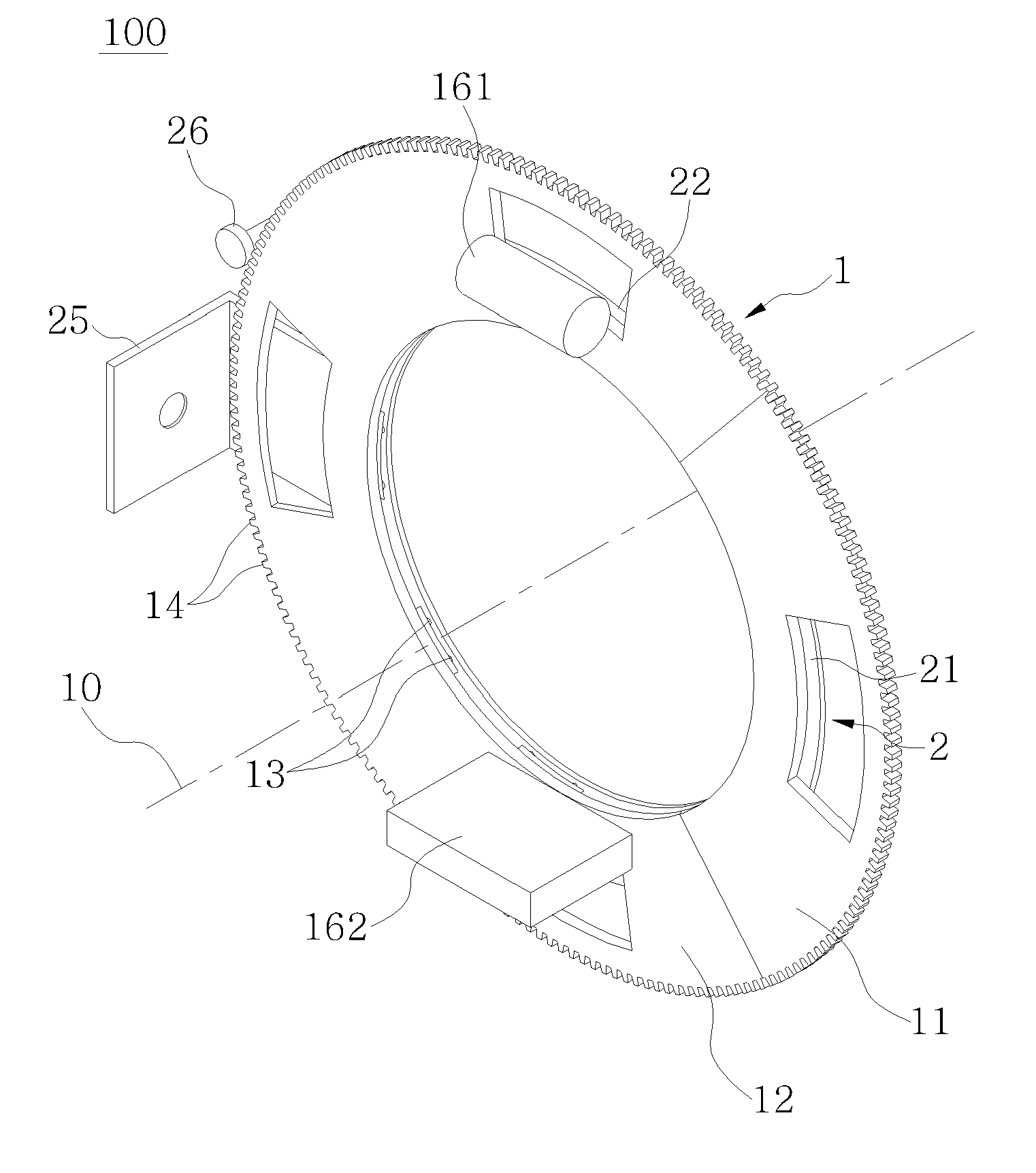
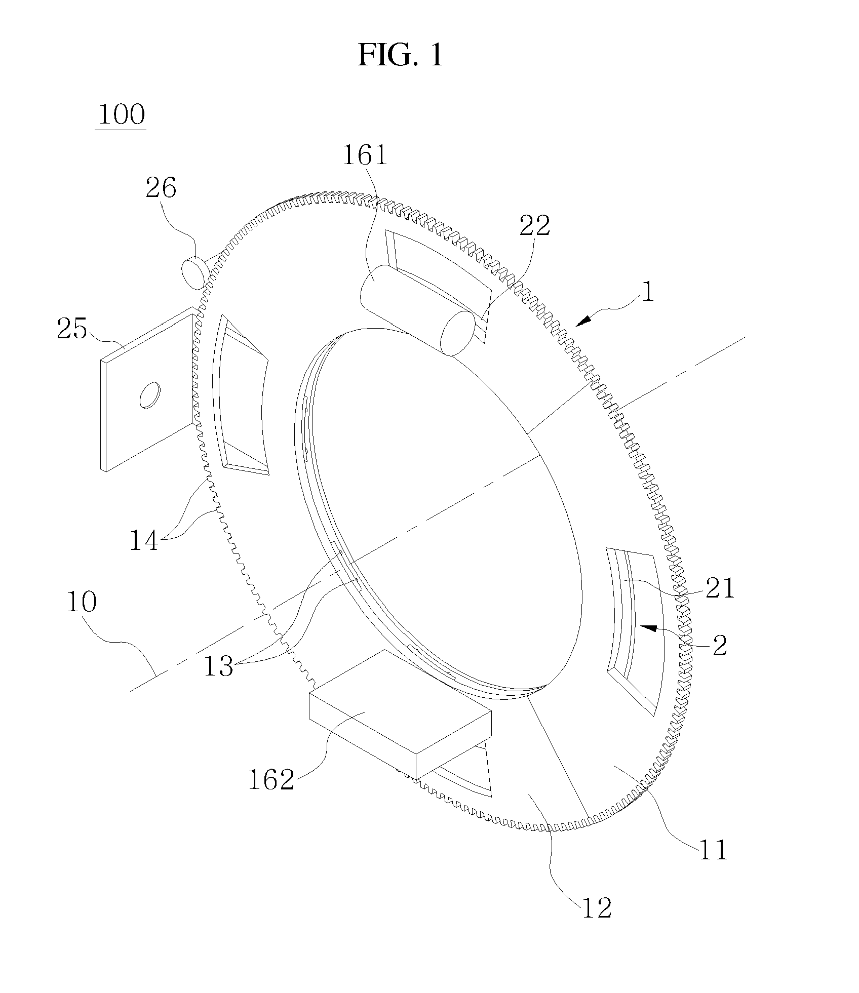
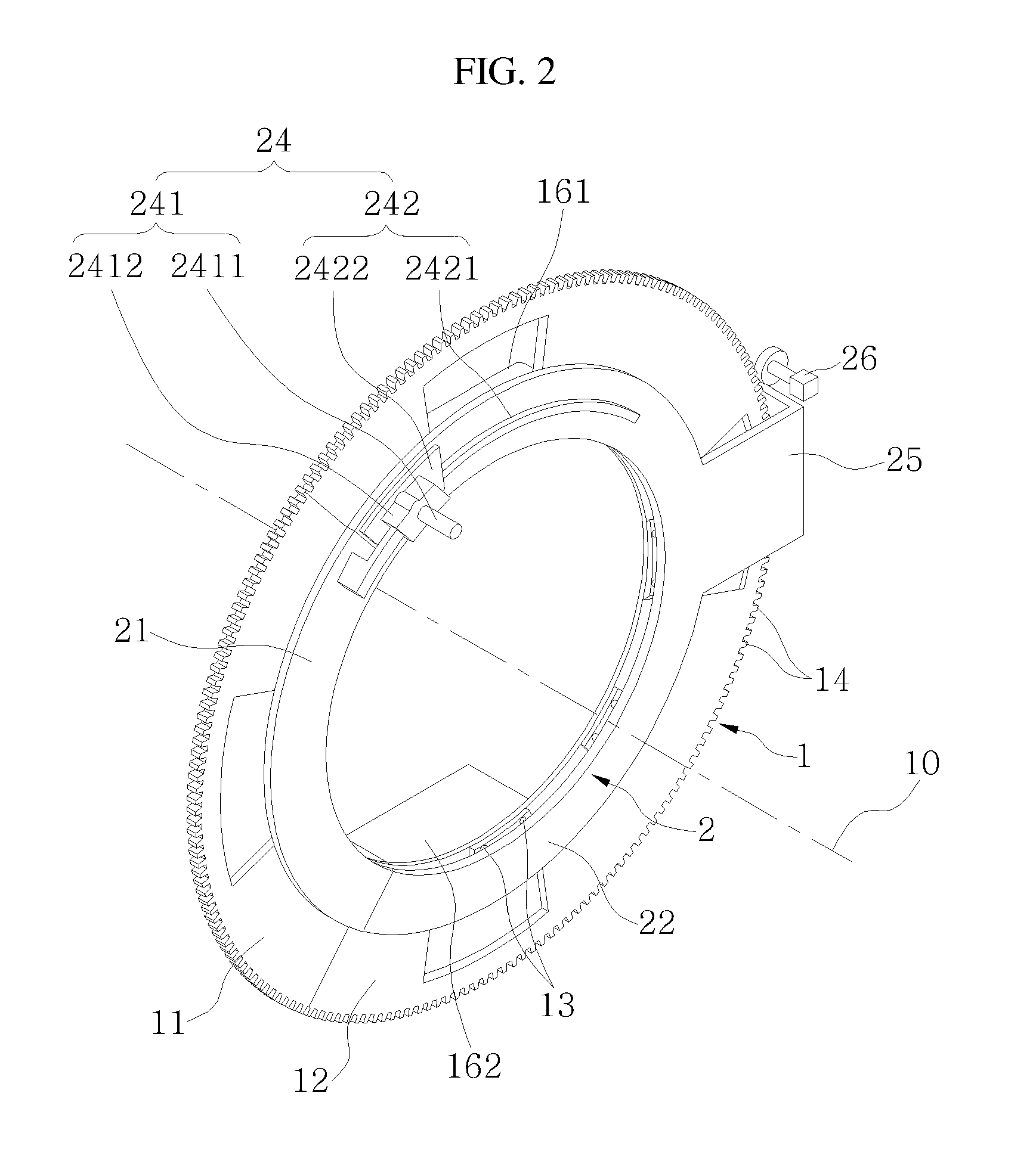
[0045]FIG. 1 is a frontal perspective view of an imaging apparatus according to an embodiment of the present invention, FIG. 2 is a rear perspective view of an imaging apparatus of FIG. 1, FIG. 3 is a front elevational view of an imaging apparatus of FIG. 1, and FIG. 4 is a rear elevational view of an imaging apparatus of FIG. 1.

[0046]Referring to FIG. 1 to FIG. 4, an imaging apparatus 100 according to an embodiment of the present invention includes a rotator 1 and a supporter 2.

[0047]First, rotator 1 will be described.

[0048]As shown in FIG. 1 to FIG. 4, rotator 1 has a shape of a...


PUM


Abstract

An imaging apparatus includes: a rotator having a shape of a perforated circular plate and rotating around a rotating axis of a center of the perforated circular plate; and a supporter having a perforated circular plate and one side of which is connected to one side of the rotator such that the rotator is restricted only to rotation movement. The supporter includes a supporter opening / closing part a part of which is separated along the rotating axis and then rotates by a predetermined angle around the rotating axis, and the rotator includes a rotator opening / closing part a part of which integrally moves with the supporter opening / closing part.

Description

CROSS-REFERENCE TO RELATED APPLICATION[0001]This application claims priority to and the benefit of Korean Patent Application No. 10-2010-0062278 filed in the Korean Intellectual Property Office on Jun. 29, 2010, the entire contents of which are incorporated herein by reference.BACKGROUND OF THE INVENTION[0002](a) Field of the Invention[0003]The present invention relates to an opening and closing module, a control method for the same, and an imaging apparatus using the same which can take multi-dimensional imaging.[0004](b) Description of the Related Art[0005]An imaging apparatus including an O-shaped gantry ring in which a hollow space is provided, and a C-shaped rotor which is disposed with the gantry ring so as to be rotatable in 360 degrees independently from the gantry ring has been introduced.[0006]Such a conventional imaging apparatus is configured that a segment of the gantry ring is separable so that object (generally a patient) can be easily moved to the center portion of t...

Claims


Application Information

Patent Timeline
IPC IPC(8): G01V3/00
CPCA61B6/4435
Inventor KIM, DUCK-JUNEJI, SANG-HOONSHON, WOONG-HEELEE, SANG-MOONAM, KYUNG-TAELEE, KWANG-HEE
Owner KOREA INST OF IND TECH
Learn More