Multiple compartment container

a multi-compartment, container technology, applied in the field of containers, can solve the problems of inconvenient consumption of convenience foods in containers, inability to maintain the desired organoleptic and texture properties of these foods, and unpleasant taste, so as to prevent leakage and minimize risk.

Inactive Publication Date: 2014-04-10
B TEK
View PDF4 Cites 11 Cited by
  • Summary
  • Abstract
  • Description
  • Claims
  • Application Information

AI Technical Summary

Benefits of technology

The present invention provides a container for packaging and storing separate products that need to be combined before use. The container has an upper and lower compartment separated by an intercompartment membrane. The membrane is connected to the lower compartment and is movable with the upper compartment. The container also has a piercing means that can be used to combine the contents of the compartments without dislodging the membrane. The container allows for easy consumption of the ready-to-use product without the need for separate utensils. The container design encourages the user to tilt the container to minimize the flow of the combined product. The invention also provides dynamic sealing structures to prevent leakage or enter of fluids into the container.

Problems solved by technology

In many cases it is impossible to maintain the desired organoleptic and texture properties of these foods when the solid and fluid component are mixed prior to prolonged storage.
For instance, when breakfast cereals are combined with milk a substantial period of time before serving, their texture and mouthfeel become unpleasant.
However, the design of the containers disclosed in these patent applications is such that the consumption of the mixed contents requires the use of a spoon or a similar utensil, making these containers not suitable for on-the-go consumption of convenience foods.
Moreover, in the case of U.S. Pat. No. 7,147,888, FR2670750, FR2831140 and U.S. Pat. No. 6,042,858, part of the divider that separates the contents of the two compartments has to be pulled out of the container, increasing the risk of spilling, for instance when inappropriate force is exerted when pulling out the divider.
In the case of U.S. Pat. No. 5,514,394 the rupture of the divider is caused by compression of one of the containers, entailing the risk of an unintentional rupture of the divider during transport.
Furthermore, the manufacture of these containers requires sealing techniques that are not customary to the food and beverage industry.
Disadvantageously, consumption of food and beverage products using such containers requires special attention from the consumer to control the dual supply of the contents of each compartment.
Disadvantageously, however, the rupturing means is conceived such that, after its actuation, the very own structure of the rupturing means or components thereof hampers the flow of contents from one compartment to the other.
Therefore, containers according to WO200053507, U.S. Pat. No. 7,740,134, U.S. Pat. No. 7,055,685 U.S. Pat. No. 7,850,072, and WO2010057452 are not suitable for mixing and consuming single handed a mixture of the contents of the two compartments, in particular in case one of the two compartments comprises particulate solid material.
Before the consumer can consume the mixed contents of the blister and the lower compartment, the blister has to be removed after its rupturing, which is not convenient.
Moreover, by exerting pressure on the blister, the contents of the blister are at risk to be crushed or otherwise damaged.
This problem is also inherent to the containers disclosed in DE29907740, which comprise two compartments that are separated by a piercable membrane, and in which the piercing of this membrane requires the compression of one of the compartments.
The containers disclosed in DE29907740 have the further disadvantage that the entire top compartment as well as the pierced membrane have to be removed before the mixed contents of the two compartments can be accessed.
Disadvantageously, the upper compartment comprises three circumferential walls going from top to bottom of the upper compartment, which requires a significant amount of plastic material, in particular when the dimensions of the upper compartment are considerably larger than those of a traditional bottle cap.
Moreover, the cap comprising the upper compartment of the container comprises 3 members, which increases the costs of production and assembly of the cap.
Moreover, the evacuation of material from the upper compartment is further hampered by said central stem, in particular in case such material comprises particulate solids.
The caps according to WO200108996 and U.S. Pat. No. 7,337,921 are not suitable for piercing a discrete sealing membrane sealed on the bottle compartment below the cap.
Disadvantageously, the cap of U.S. Pat. No. 6,105,760 situated above the blister has two circumferential walls going from top to bottom of the upper compartment, which requires a significant amount of plastic material, in particular when the dimensions of the upper compartment are considerably larger than those of a traditional bottle cap.
Such high number of members disadvantageously increases the cost of production and assembly of the container.

Method used


Image

  • Multiple compartment container
  • Multiple compartment container
  • Multiple compartment container

Examples


example 1

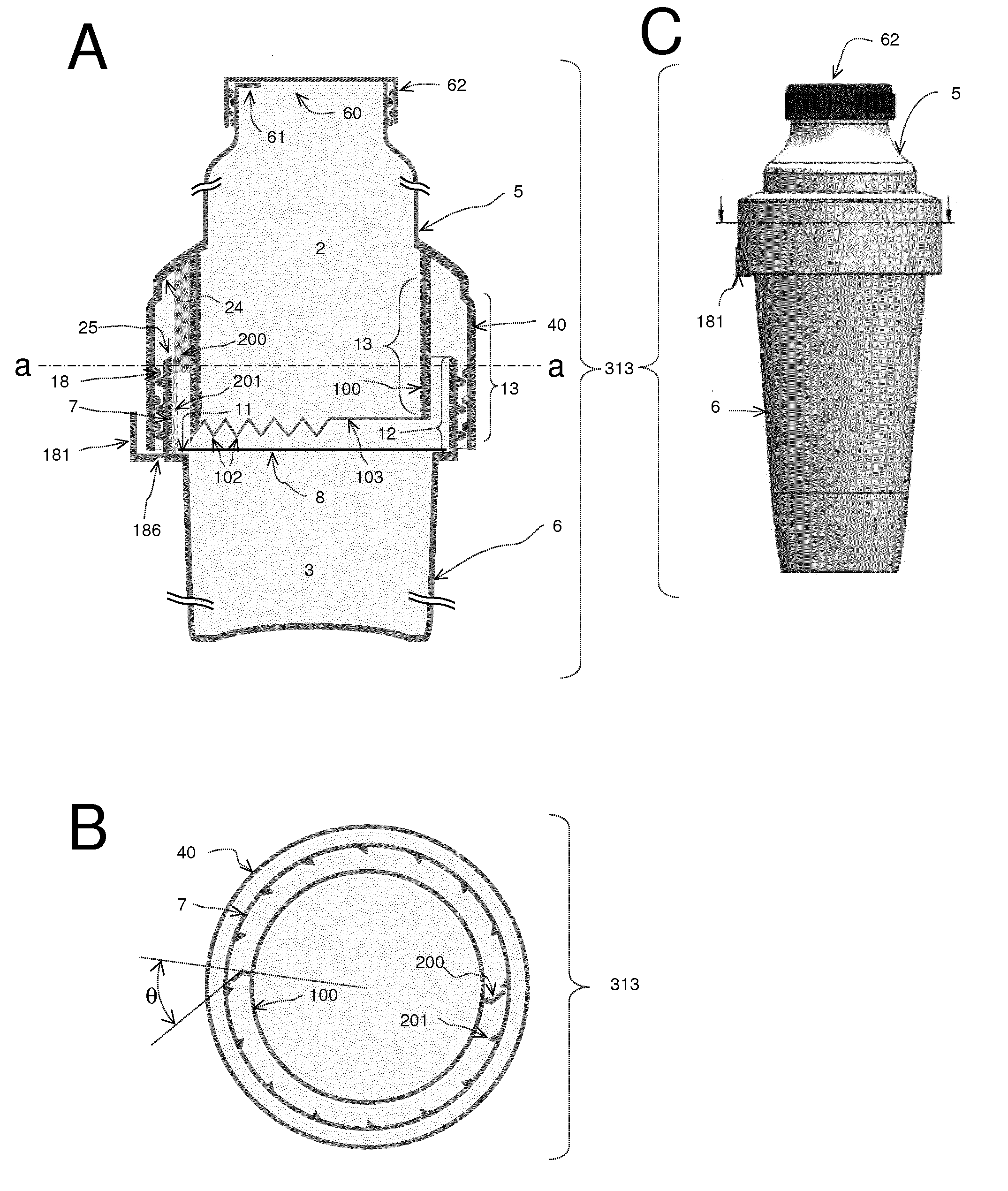
[0155]A particular embodiment of the container according to the present invention is presented in FIGS. 49 and 50. The container of this embodiment is an elaboration of the embodiment schematically represented in FIG. 2. The container (313) according to this illustrative embodiment comprises an upper (2) and lower compartment (3) separated by an intercompartment membrane (8) and is obtained by assembling two individual members, referred to as the upper (311) and lower member (312). Preferably, the upper (311) and lower member (312) are made in a plastic material using injection moulding.

[0156]The lower member (312) has a cup shape and comprises a circumferential rim (11) from which extends upwards a circumferential collar (7). At its inner side said circumferential collar (7) comprises a plurality of longitudinal ridges (201). At its outer side the circumferential collar (7) comprises part of a guidance means (18) in the form of external helical threads (170). The lower member (312)...

example 2

[0161]A particular embodiment of the container according to the present invention is presented in FIG. 51. The container of this example is an elaboration of the embodiment schematically represented in FIG. 3. The container (323) according to this illustrative embodiment comprises an upper (2) and lower compartment (3) separated by an intercompartment membrane (8) and is obtained by assembling two individual members, referred to as the upper member (321) and lower member (322). Preferably, the upper member (321) and lower member (322) are made in a plastic material using injection moulding.

[0162]The lower member (322) has a cup shape and comprises a circumferential rim (11) from which extends upwards a circumferential collar (7), which at its top is connected via a top rim (46) to an external circumferential wall (42) depending downwards from said top rim (46). The external circumferential wall (42) of the lower member (322) has an internally recessed zone (204), from which extends ...

example 3

[0166]A particular embodiment of the container according to the present invention is presented in FIG. 52. The container of this example is an elaboration of the embodiment schematically represented in FIG. 4. The container (333) according to this illustrative embodiment comprises an upper (2) and lower compartment (3) separated by an intercompartment membrane (8) and is obtained by assembling two individual members, referred to as the upper (331) and lower member (332). Preferably, the upper (331) and lower member (332) are made in a plastic material using injection moulding.

[0167]The lower member (332) has a cup shape and comprises a circumferential rim (11) from which extends upwards an internal (7) and external (44) circumferential collar. A rim section (47) connects at least part of the bottom end of the external circumferential collar (44) with bottom end of the internal circumferential collar (7). The internal circumferential collar (7) comprises at its outer side a circumfer...


PUM


Abstract

The present invention provides a container suitable for the packaging and storage in separate compartments of at least two products, which need to be combined to prepare a ready-to-use product, such as a ready-to-eat food product. When the preparation of the ready-to-use product is desired, the container of the present invention allows to easily combine the contents of said compartments and to evacuate the combined products from the container through a closable opening without dislodging any one of the compartments from one another. In case the container is used to package and store components of a ready-to-eat food product, it is preferred that the design of the container allows for the practical consumption of the prepared ready-to-eat food directly from the container.

Description

FIELD OF THE INVENTION[0001]The present invention relates to containers for storing items separately and mixing them such as a container suitable for the separate packaging and storage of at least two components, which need to be combined in the preparation of a ready-to-use product, such as a ready-to-eat food product. The container of the present invention is further designed to facilitate the mixing of said components at the moment the preparation of the ready-to-use product is desired.BACKGROUND OF THE INVENTION[0002]Upon serving, many food products comprise a liquid or colloidal liquid phase wherein solid particulate matter is mixed or suspended. In the preparation of such foods, the particulate solids are added to the liquid or colloidal liquid phase shortly before or at the moment of serving. In many cases it is impossible to maintain the desired organoleptic and texture properties of these foods when the solid and fluid component are mixed prior to prolonged storage. For ins...

Claims


Application Information

Patent Timeline
IPC IPC(8): B65D25/08
CPCB65D25/08B65D51/2835B65D81/3211
Inventor BROEKAERT, WILLEMFRANCOIS, ISABELLEVERAVERBEKE, WIMHAGEN, GEOLESCROART, OLIVIER
Owner B TEK
Why Eureka
Try Eureka