Method for avoiding artefacts during serial block face imaging

Active Publication Date: 2014-04-03
CARL ZEISS MICROSCOPY GMBH
View PDF10 Cites 20 Cited by
  • Summary
  • Abstract
  • Description
  • Claims
  • Application Information

AI Technical Summary

Benefits of technology

The patent text discusses how artifacts can occur when preparing and imaging a sample. These artifacts can make it difficult to accurately identify and analyze the sample details. The technical effect of this patent is to find a way to prevent artifacts from occurring, which will improve the accuracy and usefulness of the resulting images.

Problems solved by technology

What is disadvantageous about the last-mentioned method is that it is very time-consuming and ions are implanted into the sample material.

Method used


Image

  • Method for avoiding artefacts during serial block face imaging
  • Method for avoiding artefacts during serial block face imaging
  • Method for avoiding artefacts during serial block face imaging

Examples


Embodiment Construction

[0038]Exemplary embodiments of the invention are explained below with reference to figures. In this case, components which correspond to one another with regard to their structure and function are provided with reference signs which have the same numerals that are supplemented by an additional letter for differentiation purposes.

[0039]FIG. 1 schematically shows an apparatus suitable for performing the method according to the invention.

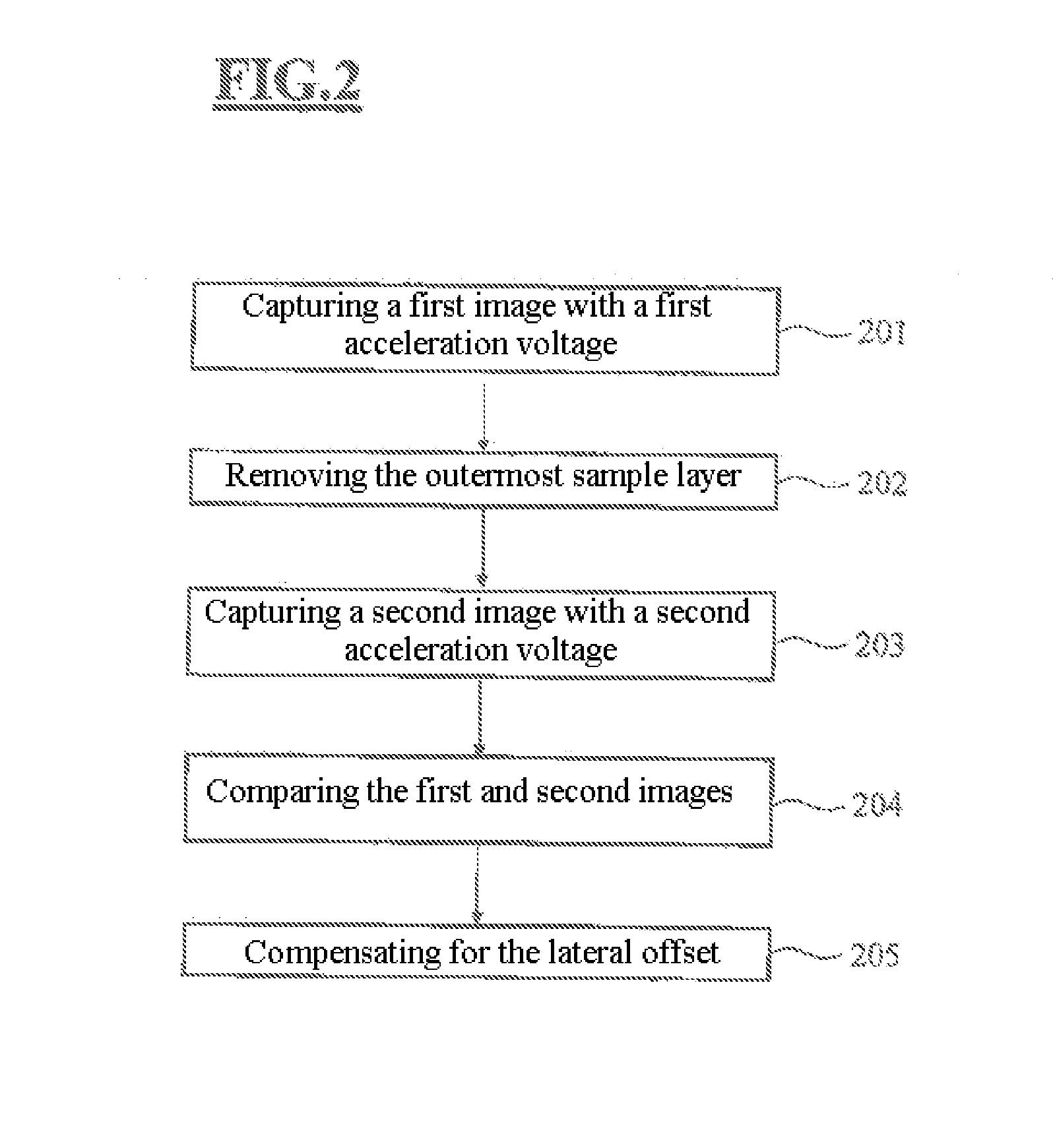
[0040]FIG. 2 shows a flowchart of the method according to the invention.

[0041]FIGS. 3a to 3c show by way of example one embodiment of the method according to the invention.

[0042]FIG. 4 shows by way of example a further advantageous embodiment.

[0043]FIGS. 5 to 7 show flowcharts of further specific embodiments of the method according to the invention.

[0044]FIG. 8 shows an extension of the method according to the invention.

[0045]FIG. 1 shows an apparatus suitable for performing the method according to the invention. The apparatus comprises a particle-opti...


PUM


Abstract

A method includes capturing a first image of the sample via a detector, wherein the particles of the primary particle beam have a first average energy so that the interaction products detected by the detector predominantly contain sample information from a sample layer lying below the sample surface. The method also includes removing the outermost sample layer with the aid of the cutting device, and capturing a second image of the sample via the detector, wherein the particles of the primary particle beam have a second average energy so that the interaction products detected by the detector predominantly contain sample information from the surface layer of the sample. The method further includes calculating the lateral shift / lateral offset of the sample from a comparison of the first and second images, and compensating for the lateral offset.

Description

[0001]The invention relates to methods for identifying and compensating for and / or avoiding artifacts which can occur during serial block face imaging.[0002]Serial block face imaging is a known method which allows a three-dimensional reconstruction (3D reconstruction) of a sample to be produced. For this purpose, the sample material is brought to the form of a block and an image of a surface of the block (block face) is generated and stored. The outermost sample layer, which was imaged, is then removed. As a result, a next sample layer is uncovered, which is now the outermost sample layer. An image of this new sample surface is generated and stored. Afterwards, this sample layer in turn is removed, an image of the newly uncovered sample surface is captured and stored, and the next sample layer is again removed, and so on, until a series of images has been created and stored, on the basis of which a 3D reconstruction of the sample block can be created computationally.[0003]Serial blo...

Claims


Application Information

Patent Timeline
IPC IPC(8): H04N7/18
CPCH04N7/18G01N23/2251G01N2223/401G01N2223/418H01J37/222H01J37/28H01J2237/221H01J2237/226
Inventor LANGER, MATTHIASARNOLD, RAINERESSELING, MARKUSPALUSZYNSKI, JAROSLAW
Owner CARL ZEISS MICROSCOPY GMBH
Why Eureka
Try Eureka