Projector system and control method for the projector system
- Summary
- Abstract
- Description
- Claims
- Application Information
AI Technical Summary
Benefits of technology
Problems solved by technology
Method used
Image
Examples
embodiment
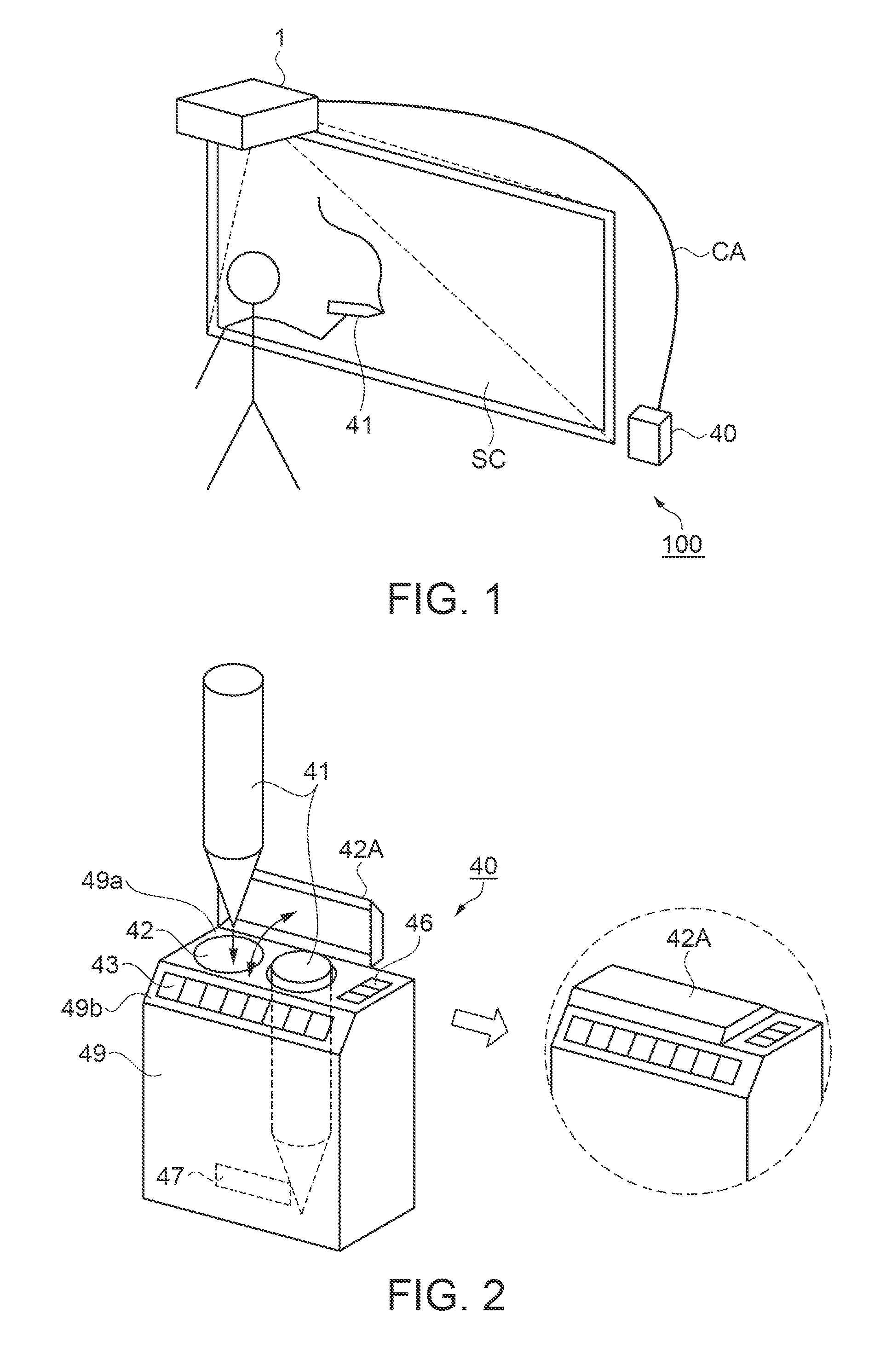
[0025]FIG. 1 is a diagram showing a setting state of a projector system 100 in this embodiment.
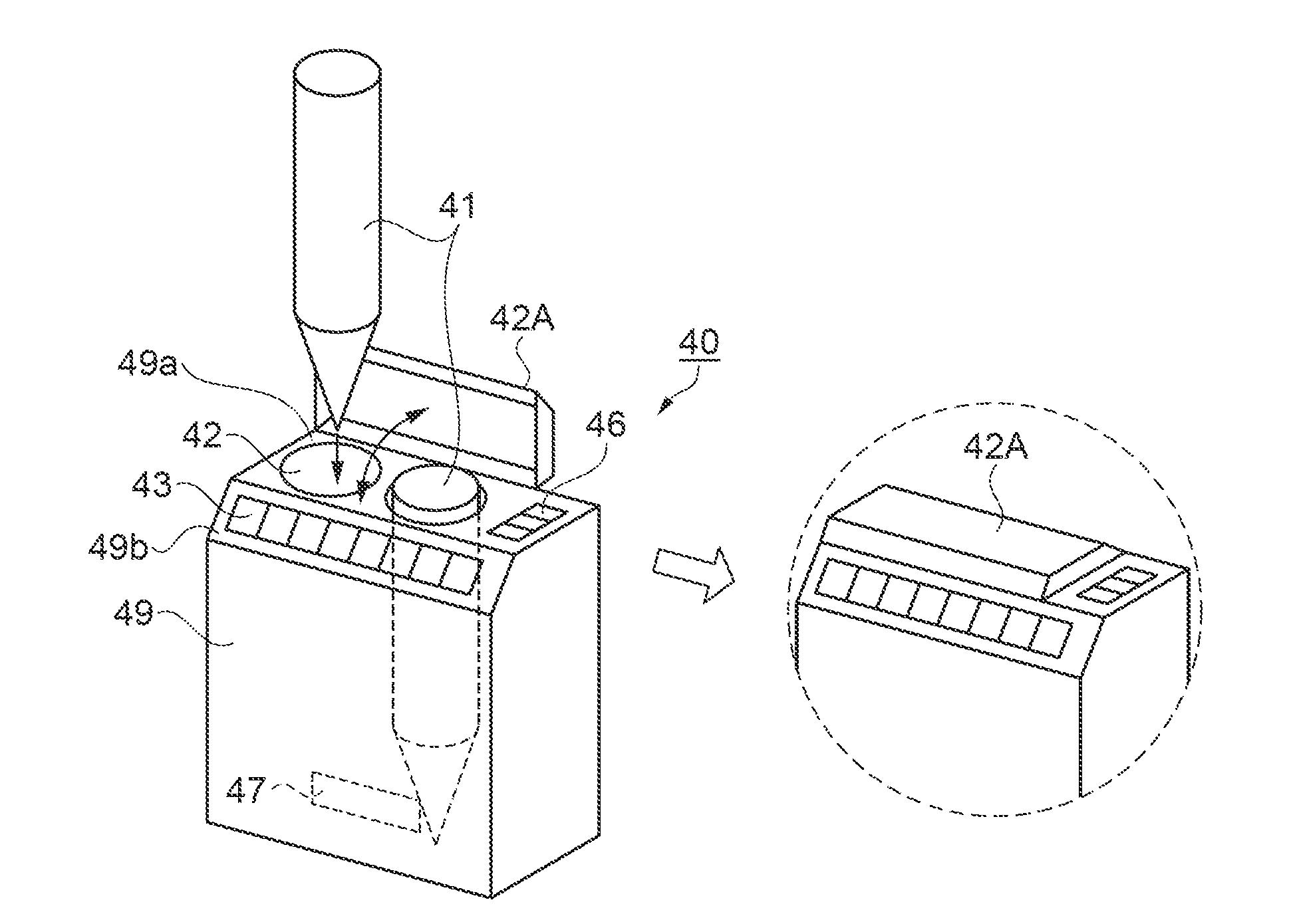
[0026]As shown in FIG. 1, the projector system 100 includes a projector 1, an input pen 41, and a pen holder 40.
[0027]When a user performs rendering operation using the input pen 41 on a projection surface of a screen SC on which the projector 1 projects an image (a projection image), a pen-operation detecting unit 25 (see FIG. 3) of the projector 1 detects an operation track of the input pen 41. The projector 1 superimposes the detected operation track of the input pen 41 on the present projection image and projects the operation track on the projection surface of the screen SC.
[0028]The projector 1 and the pen holder 40 are connected by radio or via a cable CA and can communicate with each other.
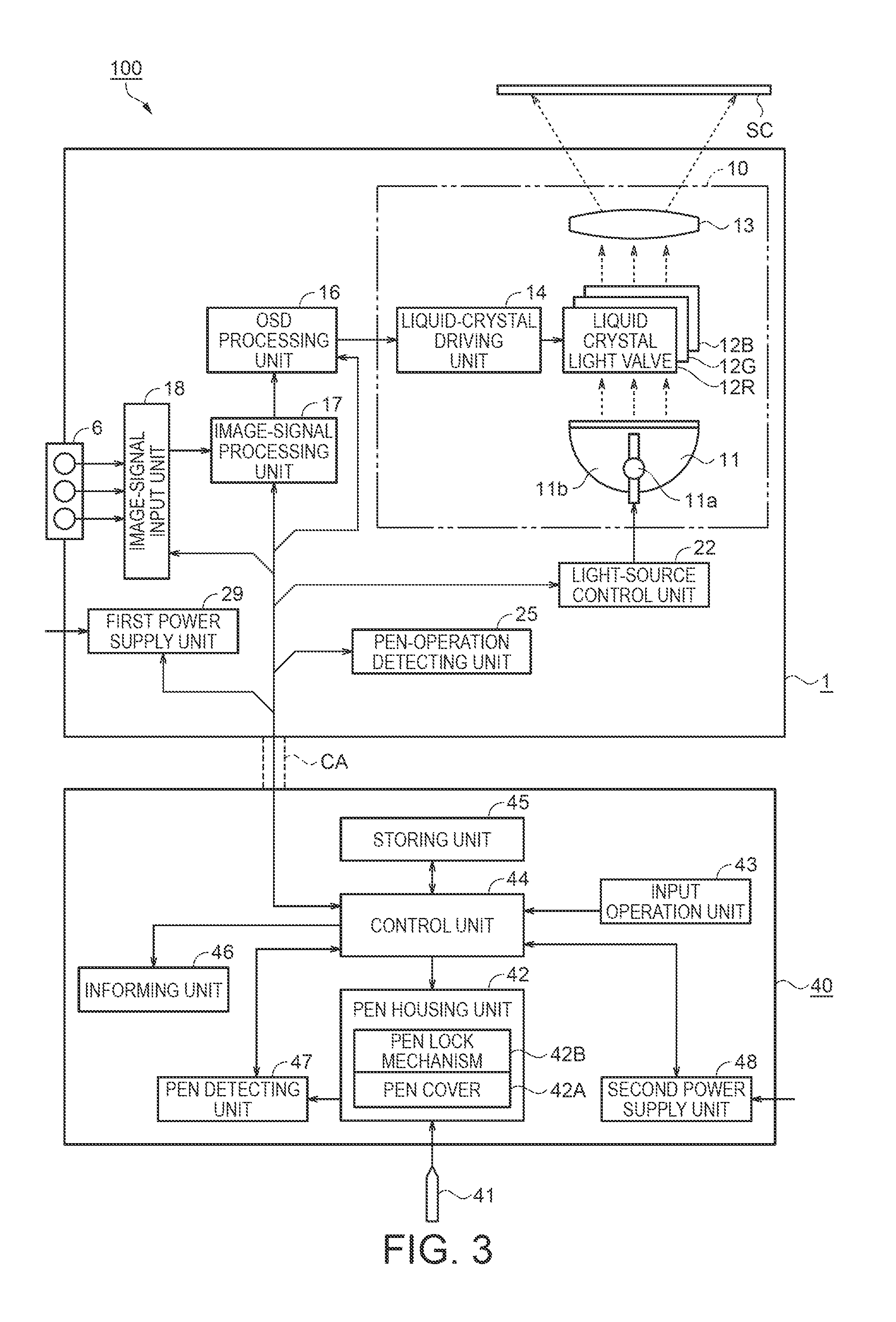
[0029]FIG. 3 is a block diagram showing a circuit configuration of the projector system 100 in this embodiment.
[0030]As shown in FIG. 3, the projector system 100 includes the projector 1, the pen...
PUM
 Abstract
Description
Claims
Application Information
 - R&D
- Intellectual Property
- Life Sciences
- Materials
- Tech Scout
- Unparalleled Data Quality
- Higher Quality Content
- 60% Fewer Hallucinations
Browse by: Latest US Patents, China's latest patents, Technical Efficacy Thesaurus, Application Domain, Technology Topic, Popular Technical Reports.
© 2025 PatSnap. All rights reserved.Legal|Privacy policy|Modern Slavery Act Transparency Statement|Sitemap|About US| Contact US: help@patsnap.com


