Eureka AIR delivers breakthrough ideas for toughest innovation challenges, trusted by R&D personnel around the world.

Method and system for predicting the serviceable life of a component

a technology for components and service life, applied in the field of method for predicting the serviceable life of components, can solve problems such as non-hazardous cracks in detection features, and achieve the effect of easy implementation and quick detection

Inactive Publication Date: 2014-03-20
ROLLS ROYCE PLC
View PDF8 Cites 5 Cited by
  • Summary
  • Abstract
  • Description
  • Claims
  • Application Information

AI Technical Summary

Benefits of technology

The patent text describes a method for monitoring the health of components by monitoring changes in their topography, particularly cracks. This helps to predict when a component will fail and can prevent unnecessary replacements of still-serviceable parts. The detection feature is easy to see, making the method simple and cost-effective compared to other non-destructive testing techniques. Overall, this invention helps to prolong the useful life of components and reduce waste.

Problems solved by technology

The presence of a detection feature in the component results in a concentration of stress at the detection feature which results in the initiation of a non-hazardous crack at the detection feature.

Method used


Image

  • Method and system for predicting the serviceable life of a component
  • Method and system for predicting the serviceable life of a component
  • Method and system for predicting the serviceable life of a component

Examples


first embodiment

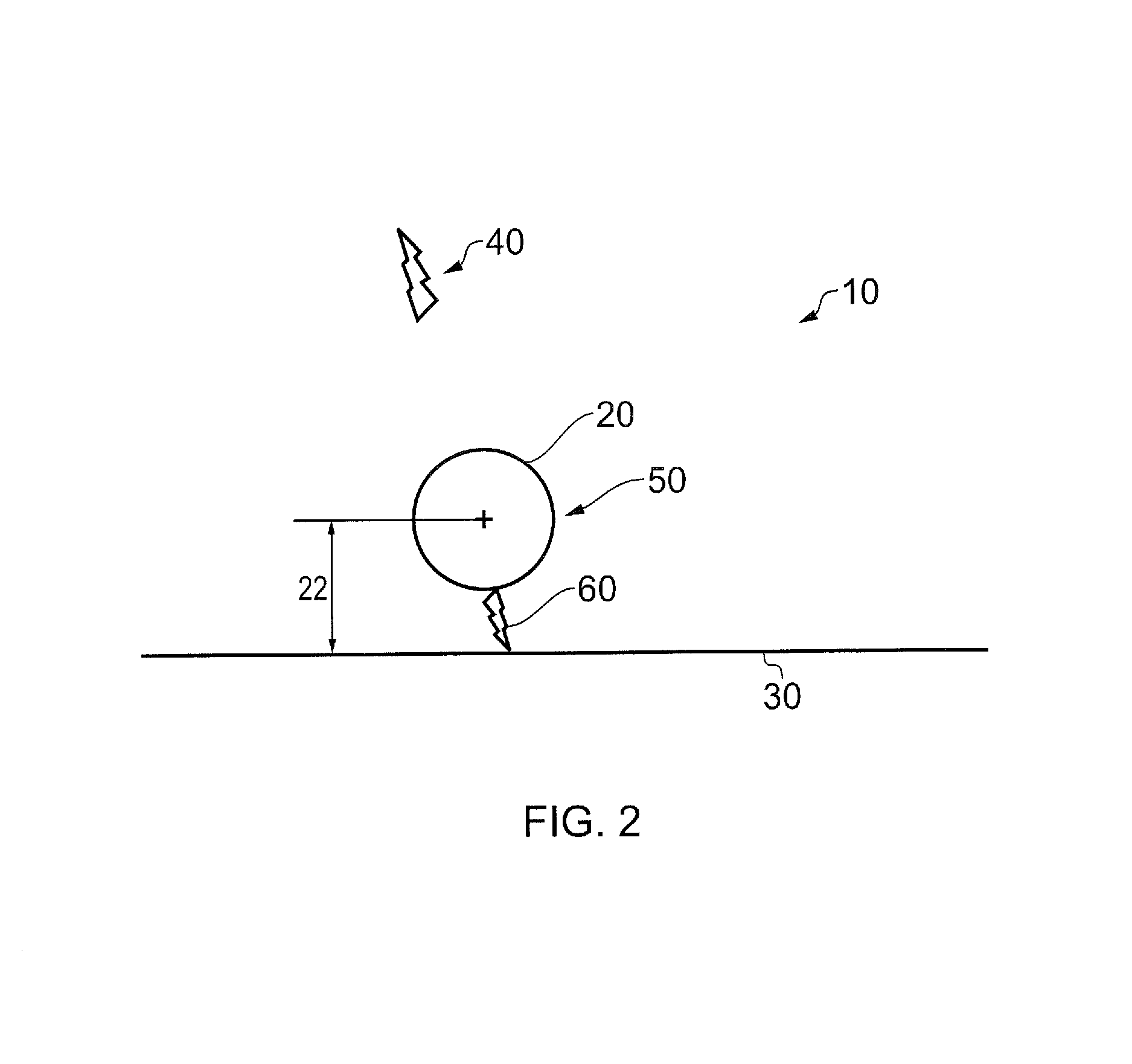
[0060]Referring to FIG. 2, a component incorporating a detection feature according to the invention is designated generally by the reference numeral 10.

[0061]In the embodiment of FIG. 2, the detection feature 20 is formed as a single topographical feature 20, in the form of a hole 50; the hole 50 being positioned at a radially outermost portion of the component. The hole 50 is located a pre-determined distance 22 from a free edge 30 of the component 10.

[0062]The distance 22 is determined such that the resulting stress concentration factor at the topographical feature 20 results in the initiation of a non-hazardous crack 60 during use of the component 10. The non-hazardous crack 60 is initiated earlier in the service life of the component 10 than any hazardous crack 40.

[0063]The size and positioning of the hole 50 is determined by any known analytical modeling technique (such as, for example, finite element analysis).

[0064]In use, the component is visually inspected for cracks at the...

second embodiment

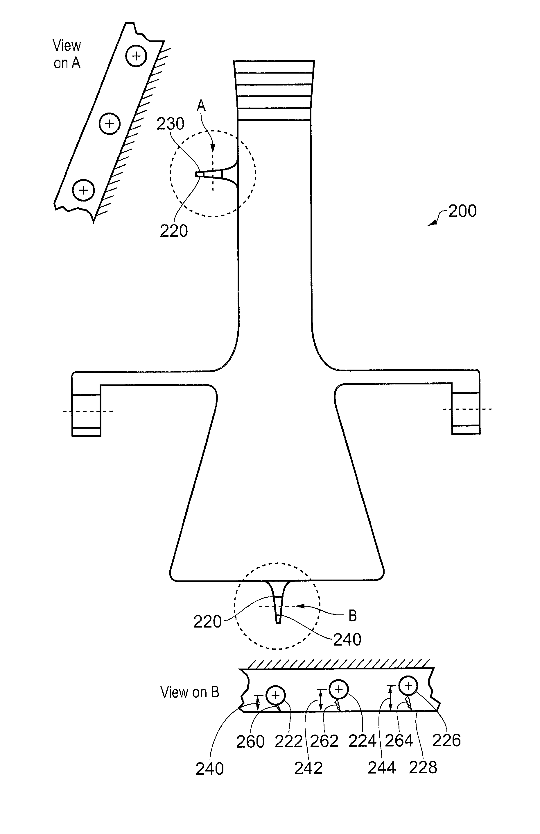
[0066]Referring to FIGS. 3A and 3B, a component incorporating a detection feature according to the invention is designated generally by the reference numeral 100. Features of the component 100 which correspond to those of component 10 have been given corresponding reference numerals for ease of reference.

[0067]The component 100 has a detection feature 120 which is formed as a topographical feature 120 comprising an array of four holes 150,152,154,156. Each of the four holes 150,152,154,156 are positioned a successively greater distance 122,124,126,128 from a free edge 30 of the component 100.

[0068]As previously described in relation to the first embodiment, the diameter and location of each of the holes 150,152,154,156 is arranged such that a non-hazardous crack 160 is initiated at a first hole 150 following a first quantity of operational hours of operation of the component 100.

[0069]The second, third and fourth holes 152,154,156 are sized and located in the component 100 such that...


PUM


Abstract

The remaining serviceable life of a component of a gas turbine engine can be predicted by monitoring one or more topographical features of the component which are arranged so as to cause a non-hazardous crack to be initiated at one or more of the topographical features during the course of operation of the gas turbine engine.

Description

[0001]This invention claims the benefit of UK Patent Application No. 1216787.0, filed on 20 Sep. 2012, which is hereby incorporated herein in its entirety.FIELD OF THE INVENTION[0002]The present invention relates to a method for predicting the serviceable life of a component subjected to service loading and a system for performing such predictive analysis. In particular, the method and system relate to components of a gas turbine engine.BACKGROUND TO THE INVENTION[0003]Component parts for aircraft jet engines are monitored at regular intervals and are generally replaced when they reach a fixed service life. This life limit is termed the Declared Safe Cyclic Life (DSCL). This replacement is undertaken irrespective of the serviceability of the component part when it reaches the DSCL.[0004]The in-service loading of aircraft gas turbine components includes a variety of stress mechanisms including complex three-dimensional stress fields, low cycle fatigue, high cycle fatigue, elasto-plas...

Claims


Application Information

Patent Timeline
IPC IPC(8): G01N3/00
CPCG01N3/00G01M5/0016G01M5/0033
Inventor BALANDIER, QUENTIN LUC
Owner ROLLS ROYCE PLC
Why Eureka
Eureka Blog
Learn More