
Intelligent use of scene and test pattern analyses for traffic camera diagnostics

Active Publication Date: 2014-03-13
CONDUENT BUSINESS SERVICES LLC
View PDF1 Cites 17 Cited by
  • Summary
  • Abstract
  • Description
  • Claims
  • Application Information

AI Technical Summary

Benefits of technology

The patent is about a method and system for detecting and responding to misalignment of a camera monitoring a desired area. The method involves acquiring a plurality of temporal frames from the camera and determining the displacement of the camera between frames. The displacement is compared to a threshold and if there is a significant displacement, the camera is automatically recalibrated or a notification of misalignment is provided to a user device. This allows for efficient and accurate detection and response to misalignment of the camera.

Problems solved by technology

However, performance of a camera deteriorates over time.
The deterioration can be gradual or sudden and can affect the camera's ability to perform its desired function.
One example of decreased performance results when the camera captures blurred images caused by a dirty or smudged lens.
Deterioration can also result from camera misorientation, which may be caused, for example, by impact to the camera housing.
Other examples of deterioration include low image contrast resulting from flash defects and failures and near field camera obstruction resulting from a variety of causes.
While total failure can easily be detected by automatic means, subtle deterioration is more difficult to detect and is further complicated by the many possible sources of deterioration including, for example, weather, vehicle speeds, and vehicle conditions.
As an example, displacement of a traffic camera's field of view (FOV) can occur when the camera position and / or orientation is moved by a force of wind, accumulated snow / ice, and / or inadequately secured camera mounts, etc.
Because traffic cameras are positioned in or near traffic flow, routine on-site camera inspections are difficult.
On-site inspections can disrupt traffic and / or place technicians at risk of oncoming traffic.
However, the labor and resources required for implementing the traffic test pattern approach are significant.
Because test pattern analysis is expensive, it should not be invoked unless clearly needed.
This drawback can be worse if this approach is used for measuring small amounts of camera misalignment (e.g. gradual deterioration over time).
Furthermore, because scene elements and noise effects can confound diagnostic signals that are extracted from the image, the performance of scene analysis for camera diagnostics varies depending on the scene.
Gaps remain and limit the capability of traffic camera diagnostics when these conventional approaches are used independent of one another.

Method used


Image

  • Intelligent use of scene and test pattern analyses for traffic camera diagnostics
  • Intelligent use of scene and test pattern analyses for traffic camera diagnostics
  • Intelligent use of scene and test pattern analyses for traffic camera diagnostics

Examples


Embodiment Construction

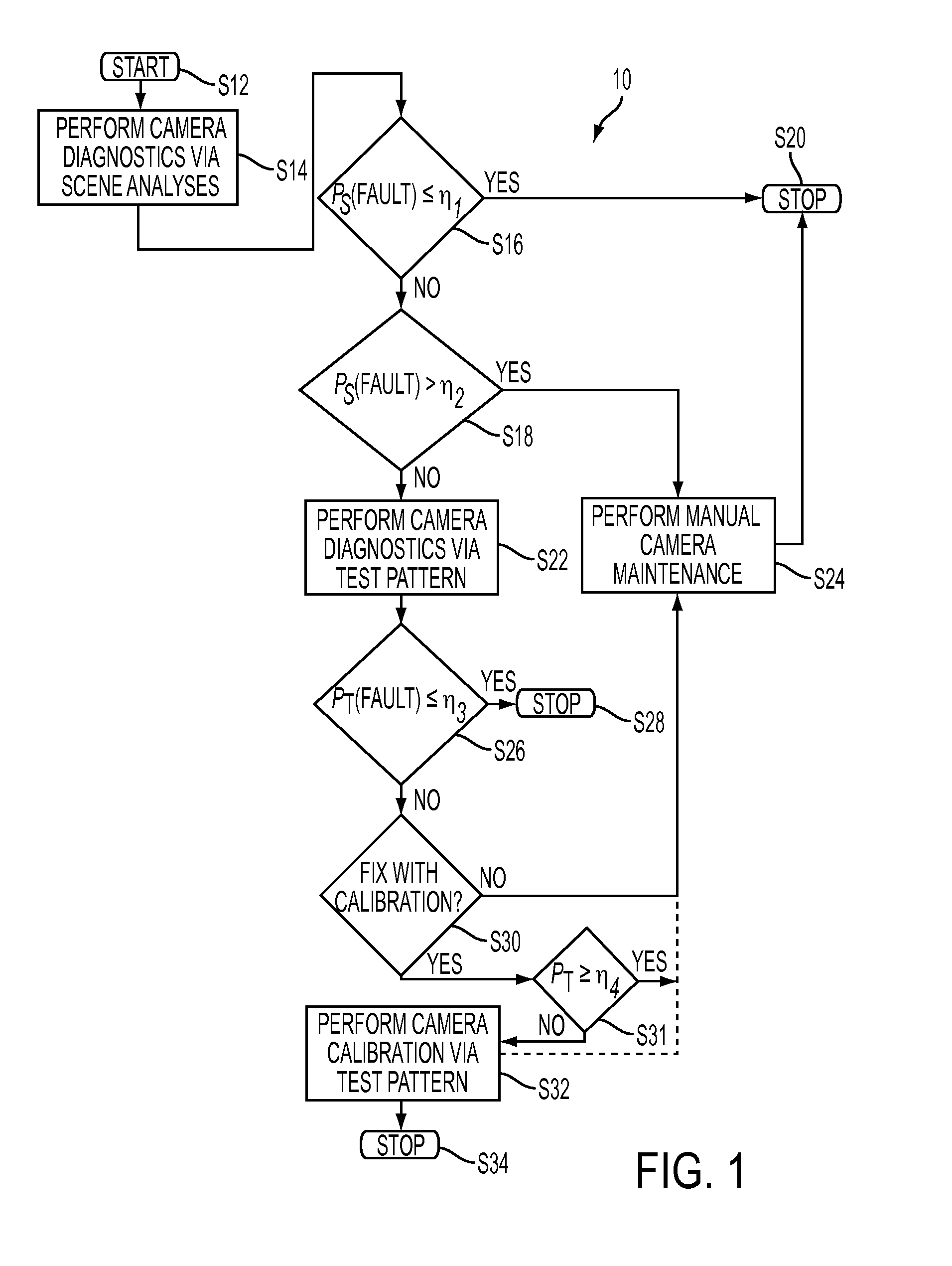
[0013]The present embodiment is directed to a system and method for performing traffic camera diagnostics using a multi-level approach including scene and test pattern analyses. Namely, the system uses thresholding results of a scene analysis to determine a possible camera fault and uses thresholding results of a test pattern analysis to confirm the suspected camera fault.

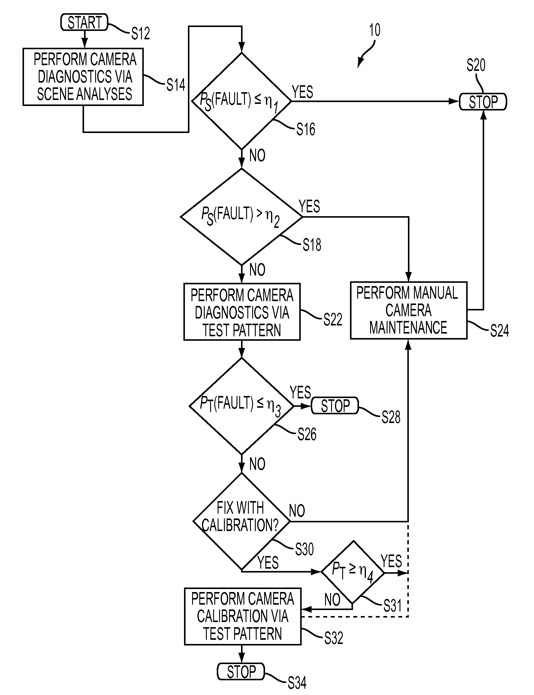
[0014]FIG. 1 provides an overview of the method 10. The system starts a diagnostic routine at S12. At S14, a scene analysis is performed on data that is extracted from an image frame of the scene that is captured by the camera. The scene analysis is used to determine a severity (i.e., a probability and / or likelihood) of the camera fault PS being tested, such as, in one example, the camera misalignment and / or displacement. The subscript S is used to denote that the camera fault PS is determined from scene analysis. The camera fault PS is compared to first and second thresholds η1 and η2 at S16, S18, whereby the seco...


PUM


Abstract

A method for determining a response to misalignment of a camera monitoring a desired area includes acquiring temporal related frames from the camera including a reference frame. A pixel location is determined of a reference object from the frames. Using the pixel location of the reference object, a displacement of the camera between a current frame and the reference frame is determined. For the displacement exceeding a first threshold, a new displacement of the camera is measured by introducing at least one additional object to a camera field of view and comparing the new displacement to a second threshold. For the new displacement not exceeding the second threshold, the camera is recalibrated using a determined pixel location and a physical location of the at least one additional object. For the new displacement exceeding the second threshold, notification is provided of a misalignment to an associated user device.

Description

BACKGROUND[0001]The present disclosure relates to a system and method for performing camera diagnostics. The system operates using a multiple phase approach to detect and confirm camera deterioration. The present disclosure finds application in traffic surveillance. However, it is appreciated that the present exemplary embodiments are also amendable to other like applications.[0002]Conventional traffic cameras are used to monitor traffic flow and survey vehicle compliance with traffic laws, rules, and regulations. A conventional traffic camera can support a variety of surveillance tasks. Generally, this type of camera selectively captures video of a scene that is being surveyed. These cameras may then transmit image data to a remote server device for further processing, or may perform some or all of the processing on-board. Because the image data is often used for fee collection and traffic enforcement, the ability of the camera to accurately render an image is essential to the perf...

Claims


Application Information

Patent Timeline
IPC IPC(8): H04N17/00
CPCH04N17/002G08G1/04
Inventor WU, WENCHENGDALAL, EDUL N.
Owner CONDUENT BUSINESS SERVICES LLC
Learn More