Dual oscillating multi-tool saw

a multi-tool saw and oscillating technology, applied in the field of dual oscillating multi-tool saws, can solve the problems of increasing the fatigue rate of the user to properly hold the oscillating multi-tool, the difficulty of holding the oscillating multi-tool in the proper position during the use of the oscillating multi-tool, etc., to reduce the fatigue of the user, improve the cutting, scraping, grinding, and reduce the vibration

Inactive Publication Date: 2014-03-13
MIG7 INFUSION +1
View PDF3 Cites 24 Cited by
  • Summary
  • Abstract
  • Description
  • Claims
  • Application Information

AI Technical Summary

Benefits of technology

The present invention is an oscillating multi-tool that addresses previous deficiencies of prior art multi-tools. It includes two or more tool attachments that can move independently of each other. The tool attachments can be the same or different in size, shape, and configuration. The multi-tool allows for improved cutting, sanding, grinding, and other material-related tasks by simultaneously moving the tool attachments in opposite directions. It reduces vibration, fatigue, and side to side forces on the user while improving cutting, scraping, and sanding accuracy. The multi-tool can also improve the speed and accuracy of cutting, scraping, and grinding tasks. The invention is designed to be used with a dedicated power tool. Overall, the present invention provides improved performance and efficiency for material-related tasks.

Problems solved by technology

Although this type of oscillating multi-tool is effective for many applications, there are several disadvantages to the use of such a device.
One disadvantage is that the oscillation of the tool connected to the oscillating multi-tool causes the oscillating multi-tool to move from side to side during the cutting, scraping, sanding, grinding, etc. of material by the oscillating multi-tool, thus making it difficult to hold the oscillating multi-tool in the proper position during the use of the oscillating multi-tool.
Also, such movement of the oscillating multi-tool can increase the rate of fatigue on the user to properly hold and position the oscillating multi-tool during the use of the oscillating multi-tool.

Method used


Image

  • Dual oscillating multi-tool saw
  • Dual oscillating multi-tool saw
  • Dual oscillating multi-tool saw

Examples


Embodiment Construction

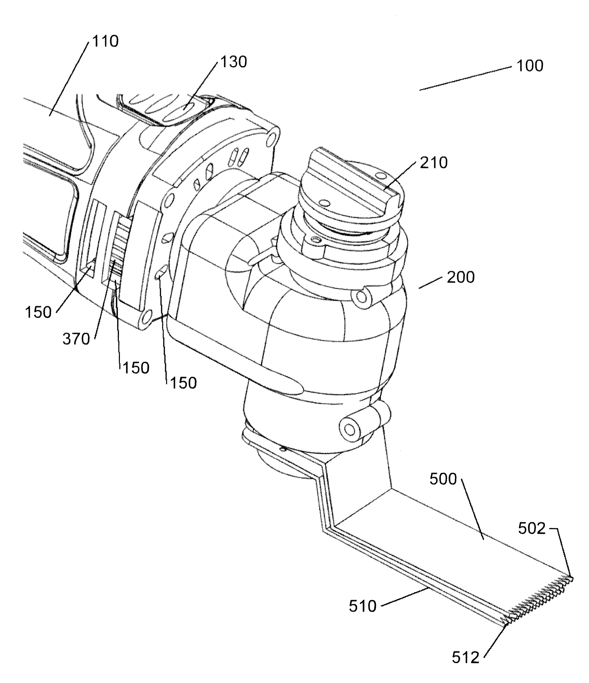
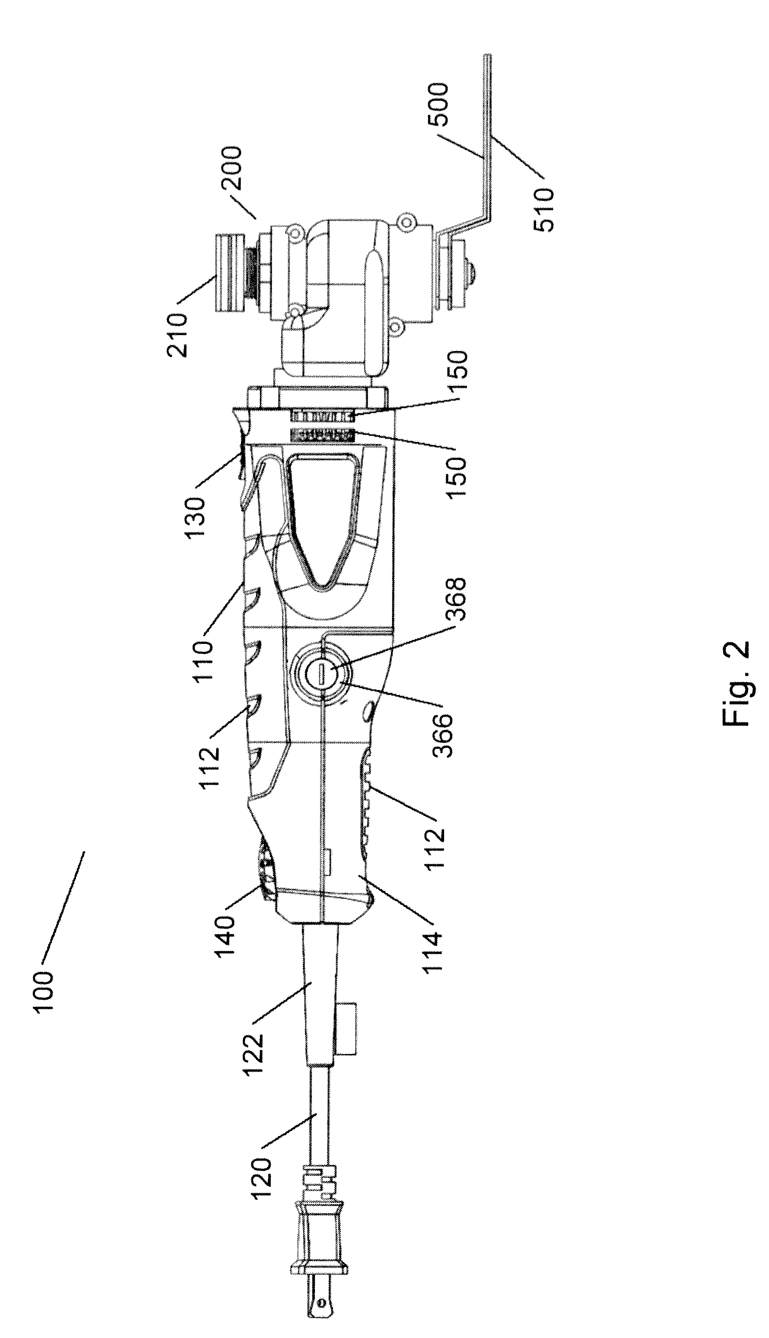
[0065]Referring now to the drawings wherein the showings are for the purpose of illustrating non-limiting embodiments of the invention only and not for the purpose of limiting same, FIGS. 1-9 illustrate non-limiting embodiments of the oscillating multi-tool in accordance with the present invention.

[0066]FIGS. 1-7 illustrate one non-limiting oscillating multi-tool in accordance with the present invention. FIGS. 8-9 illustrate another non-limiting oscillating multi-tool in accordance with the present invention. The oscillating multi-tool illustrated in FIGS. 8-9 is substantially the same as the oscillating multi-tool illustrated in FIGS. 1-7 except that the connector arrangement for the tool attachments in FIGS. 8-9 is slightly different from the connector arrangement for the tool attachments illustrated in FIGS. 1-7.

[0067]Referring now to FIGS. 1-7, there is illustrated an oscillating multi-tool having a body 110 in accordance with the present invention. The shape of the body of the ...


PUM

PropertyMeasurementUnit
Fractionaaaaaaaaaa
Perimeteraaaaaaaaaa

Abstract

An oscillating multi-tool for cutting, scraping, sanding, or grinding of material. The oscillating multi-tool includes a body, a drive system and a gear arrangement. The drive system and the gear arrangement are designed to cause first and second tool attachments to partially or fully oscillate in opposite directions. The gear arrangement is connected or interconnected to first and second tool connectors. The first tool attachment is connected to the first tool connector and the second tool attachment is connected to the second tool connector. The gear arrangement causes the first and second tool connectors to move when the drive system is activated to thereby cause the first and second tool attachments to partially or fully oscillate in opposite directions relative to one another.

Description

[0001]The present invention claims priority on U.S. Provisional Application Ser. No. 61 / 477,805 filed Apr. 21, 2011, which is incorporated herein by reference.[0002]The present invention is related to cutting, scraping, sanding, and grinding devices, particularly directed to power tools, more particularly directed to oscillating power tools, still more particularly to oscillating power tool saws that can independently oscillate at least two tool attachments, and still yet more particularly to oscillating power tool saws that can simultaneously and independently oscillate at least two tool attachments in opposite directions to one another during the use of the power tool.BACKGROUND OF THE INVENTION[0003]Oscillating multi-tools are known in the art and used to cut, scrape, sand, etc. many types of materials. Various tool attachments (e.g., E-cut blade, scraper blade, sanding pad, wood saw blade, wood / metal saw blade, grout blade, plunge blade, segmented blade, etc.) can be connected t...

Claims


Application Information

Patent Timeline
IPC IPC(8): B27B19/00B23D51/16
CPCB23D51/16B27B19/008B24B23/04B24B27/08B24B47/12B25F5/021
Inventor SOREO, ROBERTVITANTONIO, MARCJACKSON, TREVORNOTTINGHAM, JOHNSPIRK, JOHNFUCHS, JR., DONALD C.
Owner MIG7 INFUSION
Why Eureka
Try Eureka