
Laparoscope system

a technology of laparoscopy and port, which is applied in the field of microlaparoscopy systems, can solve the problems of port related complications, scars, and possibly port related pain, and the use of a plurality of 5 to 15 mm ports still leads to local pain, and achieves the effect of improving illumination capability

Active Publication Date: 2014-03-06
TELEFLEX LIFE SCI LTD
View PDF3 Cites 47 Cited by
  • Summary
  • Abstract
  • Description
  • Claims
  • Application Information

AI Technical Summary

Benefits of technology

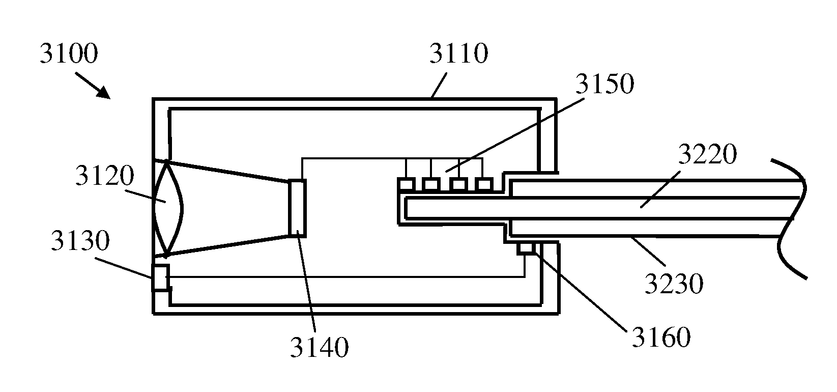
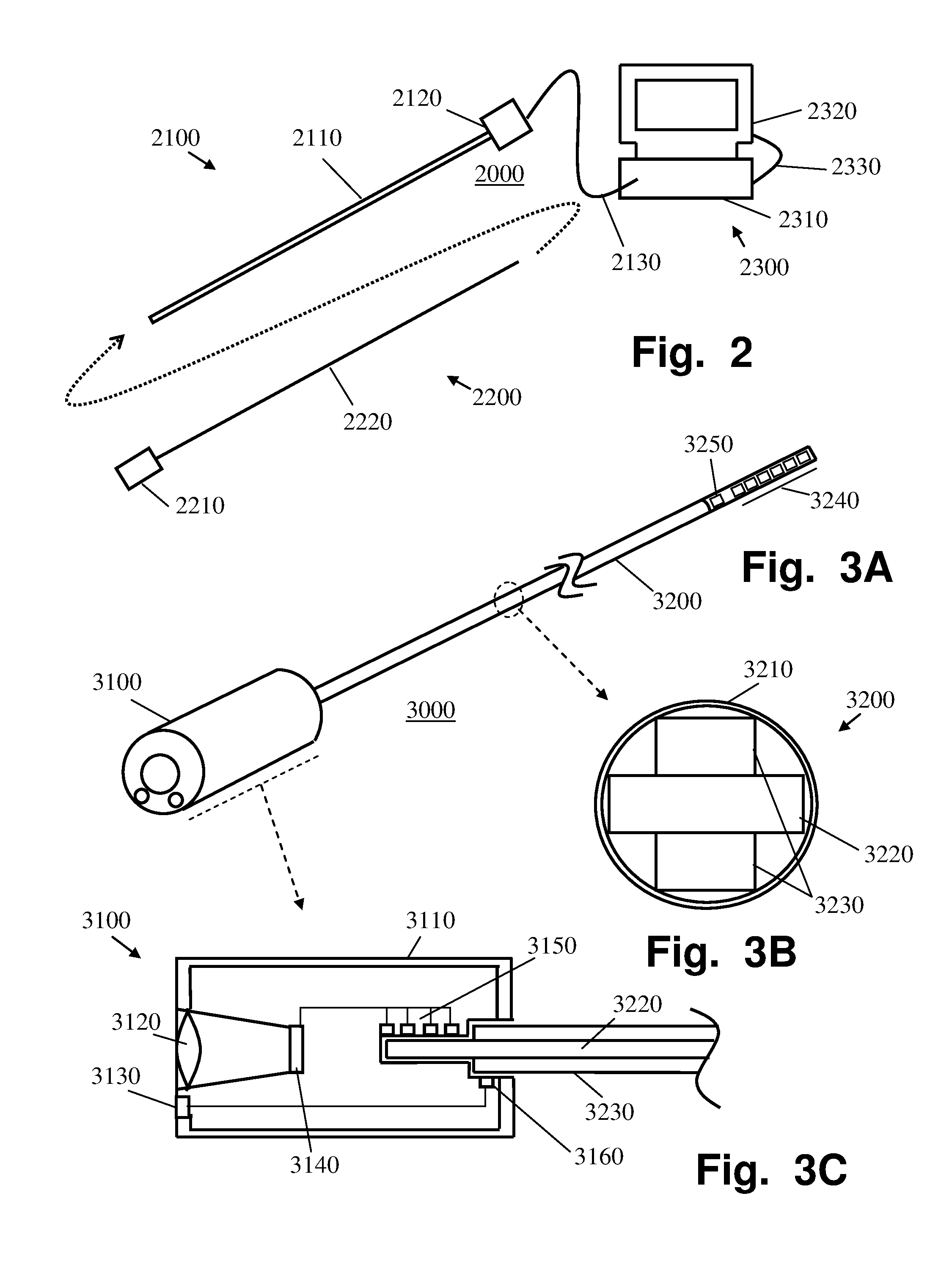
The invention is a visual device that includes an image sensor and a lens. The image sensor is larger than the elongated connector, which is connected to a camera. This allows for a wider field of view and improved depth of field. The device also uses LEDs for illumination, which provides better illumination capability. Additionally, a manipulation device for laparoscopy is also provided, which includes an insertion portion that is rigid and can protect the elongated connector when it is housed within it. The technical effects of the invention include improved image quality and improved illumination, making it easier to see and operate in laparoscopy procedures.

Problems solved by technology

Although usually considered superior in several aspects to open surgery, the use of plurality of 5 to 15 mm ports still leads to local pain, scars, and possibly port related complications such as hernia in scars and the need for one or two assistants in addition to the surgeon.
The small instruments have very slender tips which make dissection and tissue maneuveration more difficult.
Furthermore, the instrument tips may have a greater tendency to break and their removal may be cumbersome and difficult.
The small television camera, usually 3 mm or less in diameter, may be seen inferior considering its ability to capture and transfer high definition (HD) visual data, with respect to the traditional laparoscopes, due to its miniature size.
Due to the smaller effective size of the pixel, the amount or flux of the captured illumination may also be seen inferior, hence further affecting video quality.

Method used


Image

  • Laparoscope system
  • Laparoscope system
  • Laparoscope system

Examples


Embodiment Construction

[0064]It is understood that the terminology used herein is used for the purpose of describing particular embodiments only, and is not intended to limit the scope of the invention. It also is be noted that as used herein and in the appended claims, the singular forms “a,”“an,” and “the” include the plural reference unless the context clearly dictates otherwise. Thus, for example, a reference to “a lens” is a reference to one or more lenses and equivalents thereof known to those skilled in the art.

[0065]Unless defined otherwise, all technical and scientific terms used herein have the same meanings as commonly understood by one of ordinary skill in the art to which the invention pertains. The embodiments of the invention and the various features and advantageous details thereof are explained more fully with reference to the non-limiting embodiments and examples that are described and / or illustrated in the accompanying drawings and detailed in the following description. It should be not...


PUM

PropertyMeasurementUnit
outer diameteraaaaaaaaaa
maximal outer diameteraaaaaaaaaa
diameteraaaaaaaaaa

Abstract

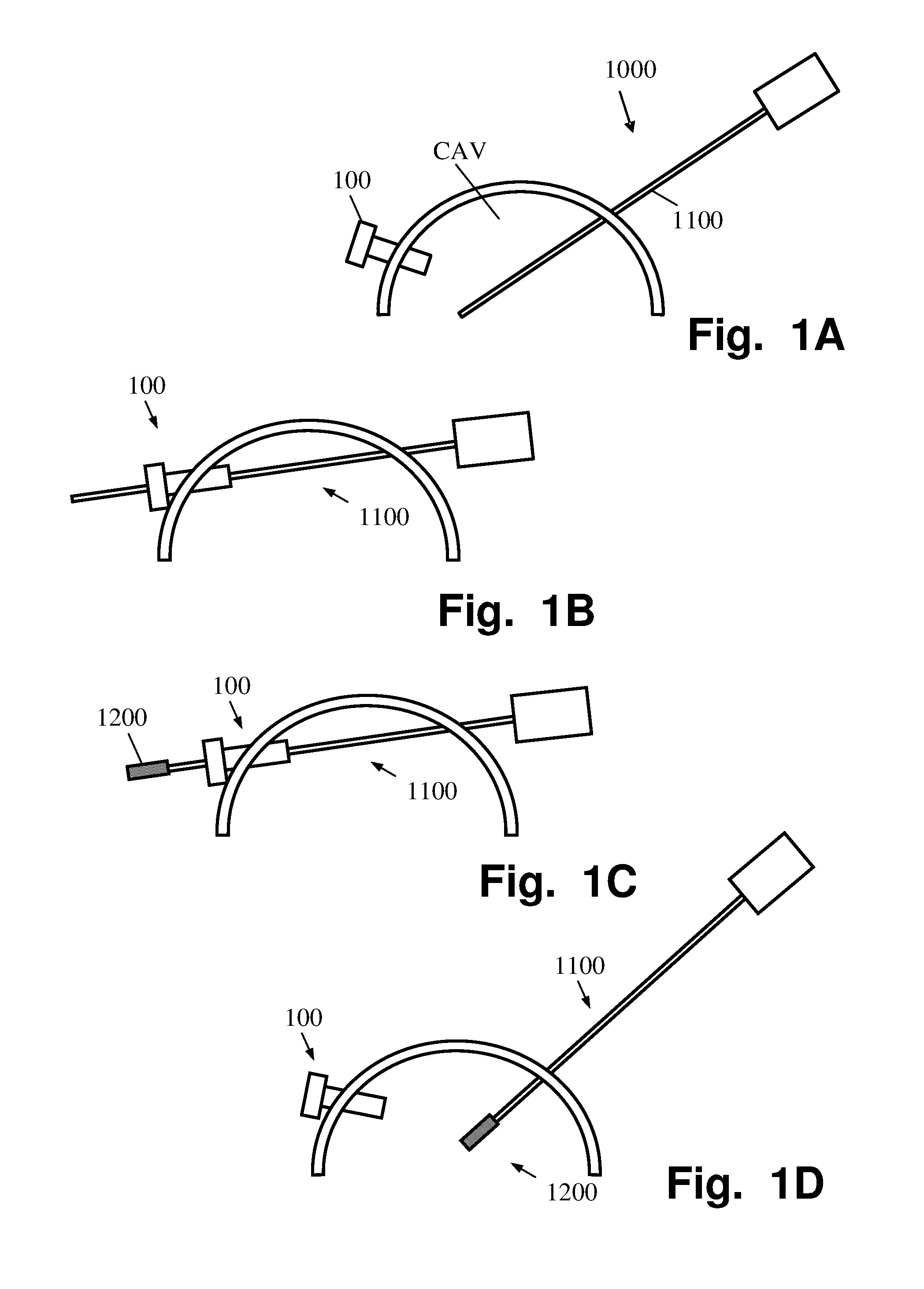
A visual system for laparoscopy comprising a visual device having a visual head member and an elongated connector; a manipulation device having a handheld operation portion, an insertion portion and a first contact element; and an external device comprising means to communicate with the vision head member, via the first contact element, when the elongated connector is mounted in an lumen of the insertion portion. The insertion portion of the manipulation device is configured to be extendable out from a body cavity through an airtight passage whereby the elongated connector is configured to be slidably mounted into the lumen of the insertion portion outside of the body cavity upon the insertion portion is withdrawn into the body cavity.

Description

FIELD OF THE INVENTION[0001]The present invention generally relates to endoscopy systems, and more specifically to micro-laparoscopy systems and methods of deployments thereof.BACKGROUND OF THE INVENTION[0002]Laparoscopic or minimally invasive surgery includes the use of several relatively small ports into the abdomen by which different types of instrumentation and accessories are introduced and used for different surgical interventions (usually performed under endoscopic vision). Although usually considered superior in several aspects to open surgery, the use of plurality of 5 to 15 mm ports still leads to local pain, scars, and possibly port related complications such as hernia in scars and the need for one or two assistants in addition to the surgeon. Laparoscopic methods and surgical device are described, for example, in U.S. Pat. Nos. 5,980,493, 7,593,777 and 7,316,699, the disclosures of which are fully incorporated herein by reference.[0003]In a relatively new laparoscopic ap...

Claims


Application Information

Patent Timeline
Patent Type & Authority Applications(United States)
IPC IPC(8): A61B1/00A61B1/04
CPCA61B1/00121A61B1/04A61B1/0011A61B1/053A61B1/0676A61B1/3132A61B1/00124A61B17/34A61B2017/00473A61B2017/00477A61B1/00105Y10T29/49117Y10T29/49826A61B90/361A61B2090/309A61B2090/306A61B1/0684
Inventor FARIN, DANNYBACHAR, YEHUDA
Owner TELEFLEX LIFE SCI LTD
Learn More