Eureka AIR delivers breakthrough ideas for toughest innovation challenges, trusted by R&D personnel around the world.

Acoustic wave generator employing fluid injector

a technology of injector and generator, applied in the field of acoustic wave generator, can solve the problems of limiting the possibility of miniaturization of speakers, affecting the sound quality of speakers, etc., and achieve the effect of improving the sound fidelity

Inactive Publication Date: 2014-03-06
TSENG HO PING
View PDF3 Cites 10 Cited by
  • Summary
  • Abstract
  • Description
  • Claims
  • Application Information

AI Technical Summary

Benefits of technology

The present invention relates to an apparatus for producing an acoustic wave using a fluid injector which can operate at frequencies that do not have a one-to-one relationship to the frequencies of the output acoustic wave, thereby enabling smaller speaker sizes for a given acoustic power. The apparatus can use one fluid injector or two fluid injectors with valves to create an acoustic wave proportional to an electrical signal. A sensor or microphone can be used to help improve fidelity of the sound. The technical effects include smaller speakers, improved frequency relationships, and improved sound quality.

Problems solved by technology

These dependencies become a problem when higher acoustic power is desired per given size.
In particular, such dependencies limit the possible miniaturization of speakers.

Method used


Image

  • Acoustic wave generator employing fluid injector
  • Acoustic wave generator employing fluid injector
  • Acoustic wave generator employing fluid injector

Examples


Embodiment Construction

[0036]It is worthy to note that any reference herein to “one embodiment” or “an embodiment” means that a particular feature, structure, or characteristic described in connection with the embodiment is included in at least one embodiment of the invention. The appearances of the phrase “in one embodiment” in various places in the specification are not necessarily all referring to the same embodiment or all embodiments.

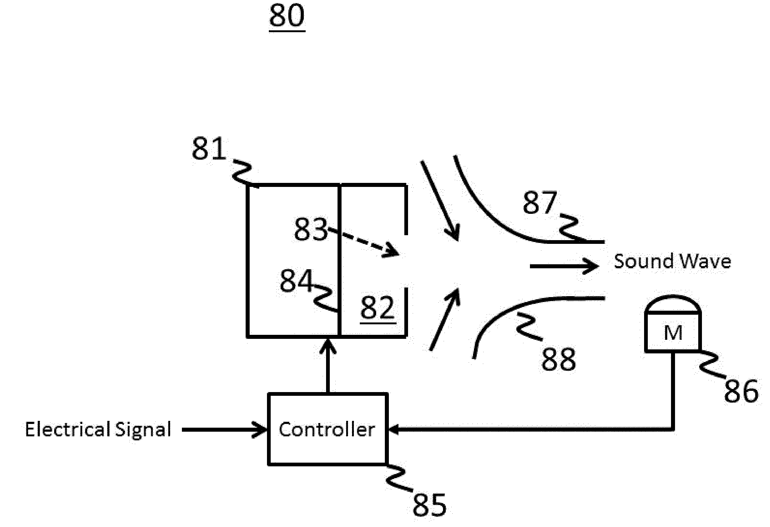
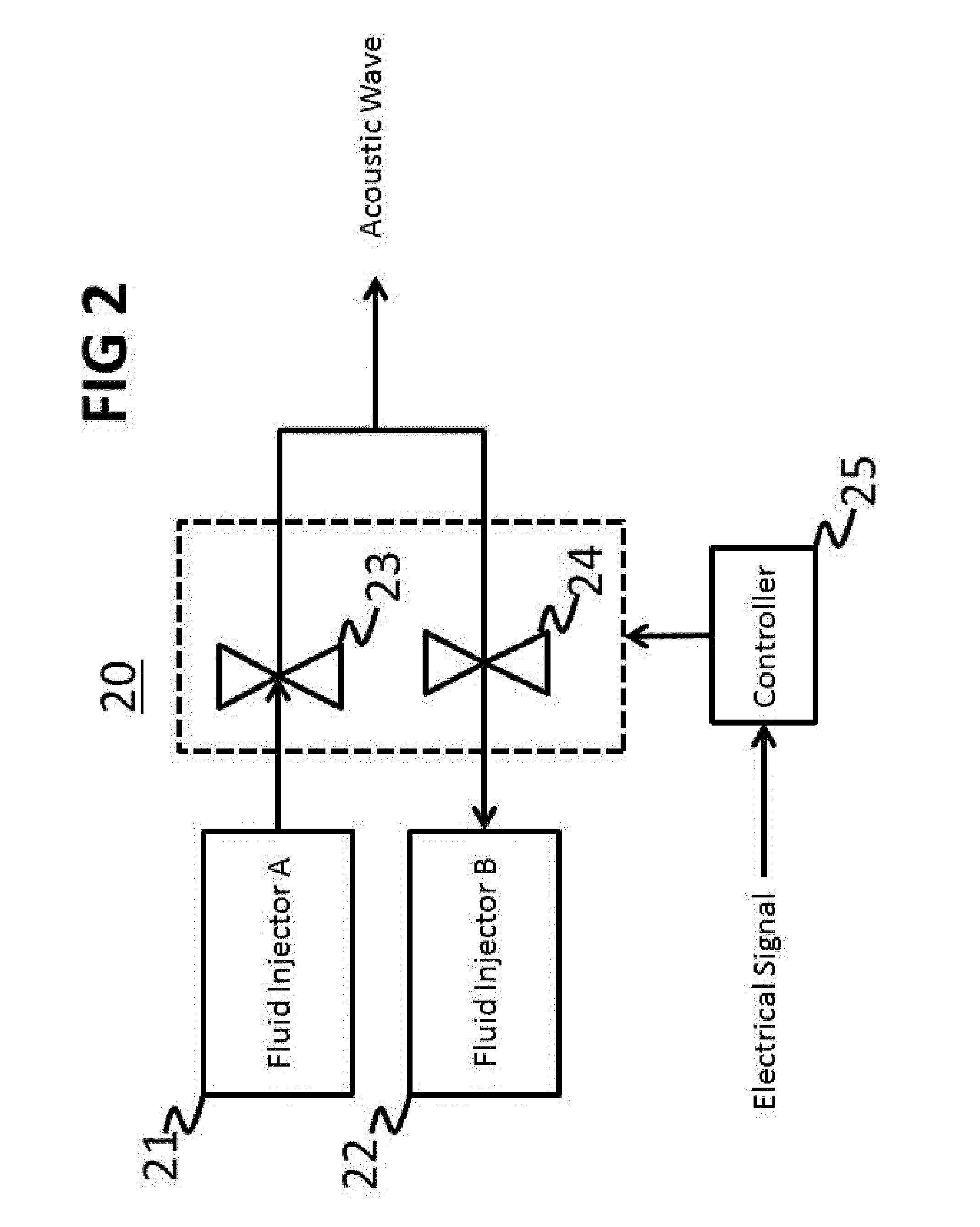
[0037]According to one aspect of the present invention, an apparatus 20 for producing an acoustic wave is shown in FIG. 2, which is a simplified diagram for such an apparatus. Devices 21 and 22 are fluid injectors (e.g., pumps, synthetic jets, pistons, turbines / propellers, etc.) capable of producing fluid flow in the directions shown by the arrows.

[0038]The present invention provides for the use of fluid injectors to create controllable acoustic waves for reproducing sound from traditional information bearing electrical signals used in audio applications. In particular, ...


PUM


Abstract

To reproduce sound in an extremely compact size, fluid injectors are used that can generate fluid flow sufficient to create a desired acoustic pressure wave, but which fluid flow operates in a manner that is decoupled from the desired acoustic pressure wave. Fluid flow within the fluid injectors needed to generate the desired acoustic pressure wave need not be directly proportional to the frequencies of the desired acoustic pressure wave. The fluid injector has a control input capable of altering fluid flow relative to a received control signal, which is generated by a controller in response to an electrical signal. The fluid injector produces fluid flow outward and inward in response to the control signal, thereby creating an acoustic wave proportional to the electrical signal. The devices herein may employ valves or not. Synthetic jets may also be used.

Description

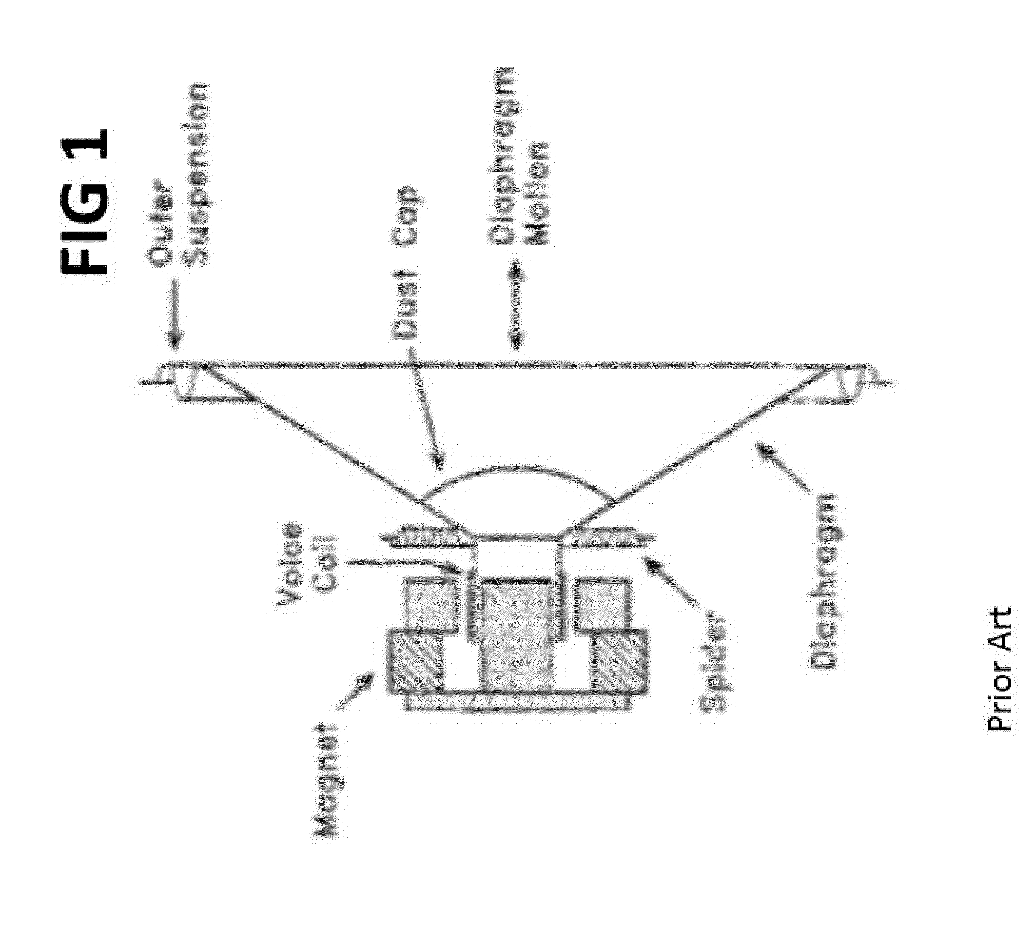
BACKGROUND[0001]The present invention relates generally to acoustical wave generators, and more particularly to an acoustic wave generator for producing audible sound waves.[0002]An acoustic wave is formed when fluid pressure, be it for gas (air or other gas) or liquid, is made to vary in time and space. This is usually effected through a device which vibrates to cause this pressure wave. In air, this is typically done with a vibrating diaphragm in a device known as a loudspeaker, which alternately compresses and rarefies the air contacting the diaphragm as it vibrates.[0003]An exemplary prior art loudspeaker is depicted in FIG. 1. In this device, the diaphragm vibrates in a range typically between 20 Hz to 20,000 Hz to create audible sound and at even higher frequencies to produce inaudible ultrasound. An applied current through the voice coil causes a deflection proportional to the current through magnetic interaction between the voice coil and magnet. As the diaphragm is caused t...

Claims


Application Information

Patent Timeline
IPC IPC(8): G10K9/08
CPCG10K7/00
Inventor TSENG, HO PING
Owner TSENG HO PING
Why Eureka
Eureka Blog
Learn More