Delivery device having a curved shaft and a straightening member for transcatheter aortic valve implantation

a delivery device and a technology for aortic valves, applied in the field of heart valve replacement, can solve the problems of aortic valve damage, aortic valves may not close properly, and it is difficult to properly align the collapsible heart valve with the valve annulus,

Active Publication Date: 2014-02-20
ST JUDE MEDICAL CARDILOGY DIV INC
View PDF14 Cites 6 Cited by
  • Summary
  • Abstract
  • Description
  • Claims
  • Application Information

AI Technical Summary

Benefits of technology

The present patent relates to a delivery device and method for implanting a prosthetic heart valve. The device includes a support member, distal sheath, outer shaft, and straightening member. The straightening member can cover the curved portion of the outer shaft and straighten it. The device also includes an outer tube which can lie within the curved portion of the outer sheath. The technical effects of this device include holding the prosthetic heart valve in a collapsed condition, exposing it for use, and maintaining its shape during delivery.

Problems solved by technology

Diseased or damaged aortic valves may not close properly and thus allow blood to flow back into the heart.
Damage to aortic valves may occur due to congenital defects, the natural aging process, infection or scarring.
Current collapsible prosthetic heart valve designs may be used in high-risk patients who may need a cardiac valve replacement, but who are not appropriate candidates for conventional open-chest, open-heart surgery.
With either technique, however, it is difficult to properly align the collapsible heart valve with the valve annulus.
This excessive force could affect the electrical conduction system of the heart.
However, reducing the stiffness of the delivery catheter shaft would likely sacrifice at least some of the columnar strength necessary for deployment and resheathing.
Steerable catheters, however, can be bulky, expensive to make and more complicated to use.

Method used


Image

  • Delivery device having a curved shaft and a straightening member for transcatheter aortic valve implantation
  • Delivery device having a curved shaft and a straightening member for transcatheter aortic valve implantation
  • Delivery device having a curved shaft and a straightening member for transcatheter aortic valve implantation

Examples


Embodiment Construction

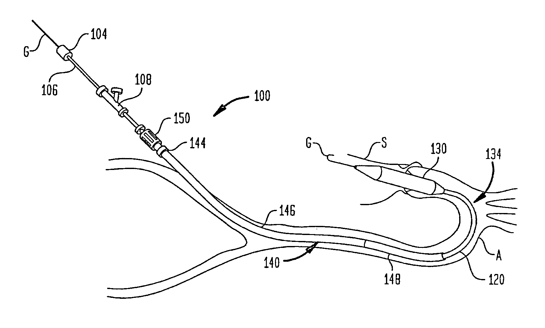
[0019]Embodiments of the presently disclosed delivery devices are described herein in detail with reference to the drawing figures, wherein like reference numerals identify similar or identical elements. In the drawings and in the description which follows, the term “proximal” refers to the end of the delivery device, or portion thereof, which is closest to the operator during use, while the term “distal” refers to the end of the delivery device, or portion thereof, which is farthest from the operator during use.

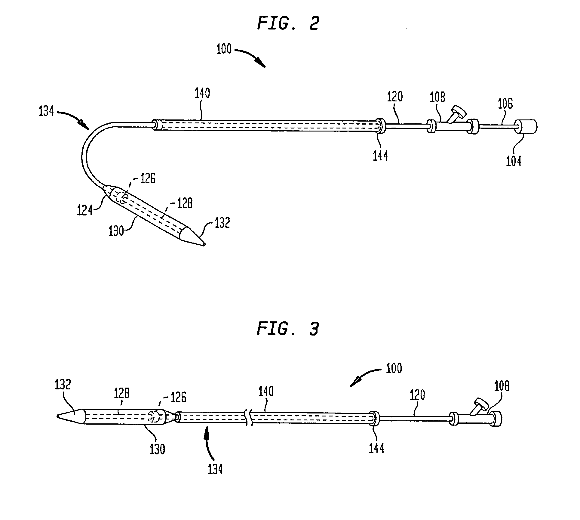
[0020]FIG. 2 illustrates a transfemoral delivery device 100 according to an embodiment of the present invention. The delivery device 100 may include an inner tube 106 having a lumen extending therethrough. A hub 104 mounted on the proximal end of the inner tube 106 is adapted for connection to another system or mechanism, such as a handle, a syringe or a mechanism for displacing the distal sheath 130. Mechanisms for displacing the distal sheath 130 are described in U.S. Prov...


PUM


Abstract

A delivery device (100) includes a support member (128), a distal sheath (130), an outer shaft (120) and a strengthening member (140). The support member is adapted to hold a prosthetic heart valve. The distal sheath is slidable relative to the support member between a first position in which the distal sheath is adapted to maintain the prosthetic heart valve in a collapsed condition, and a second position in which the distal sheath is adapted to expose the prosthetic heart valve. The outer shaft is connected to the distal sheath and has a curved portion (134). The straightening member is slidable on the outer shaft between a proximal position in which the straightening member does not cover the curved portion of the outer shaft, and a distal position in which the straightening member covers and substantially straightens at least a portion of the curved portion of the outer shaft.

Description

CROSS-REFERENCE TO RELATED APPLICATIONS[0001]This application claims the benefit of the filing date of U.S. Provisional Patent Application No. 61 / 384,549 filed Sep. 20, 2010, the disclosure of which is hereby incorporated herein by reference.BACKGROUND OF THE INVENTION[0002]The present disclosure relates to heart valve replacement and, more specifically, to devices and methods for implanting a collapsible prosthetic heart valve in a patient.[0003]A healthy aortic valve acts as a one-way valve, opening to allow blood to flow out of the left ventricle of the heart, and then closing to prevent blood from flowing back into the heart. Diseased or damaged aortic valves may not close properly and thus allow blood to flow back into the heart. Damage to aortic valves may occur due to congenital defects, the natural aging process, infection or scarring. Diseased or damaged aortic valves sometimes need to be replaced to prevent heart failure. In such cases, collapsible prosthetic heart valves ...

Claims


Application Information

Patent Timeline
IPC IPC(8): A61F2/24
CPCA61F2/2436A61F2250/0018A61F2250/0019A61F2250/0029A61M25/0041A61M25/01A61M2025/0004
Inventor WANG, HUISUNTHOMAS, RALPH JOSEPH
Owner ST JUDE MEDICAL CARDILOGY DIV INC
Why Eureka
Try Eureka