Spiral brace

Inactive Publication Date: 2014-02-20
3D SYST INC
View PDF2 Cites 7 Cited by
  • Summary
  • Abstract
  • Description
  • Claims
  • Application Information

AI Technical Summary

Benefits of technology

The patent describes a spiral brace that can be used to support and immobilize a limb. The brace is made of a thin, elastic material that can be easily worn under clothing and is comfortable to wear. It can be designed to provide support for the limb and prevent bending movements. The brace can be customized to fit different limbs and can be easily adjusted to different needs. It can be used to prevent carpal tunnel injury or other medical conditions. The brace can be designed based on a three-dimensional digital representation of the limb surface topography, which allows for a close fit without the need for padding. The brace can be made of a hard plastic material that provides structural strength and can be designed to be lightweight and thin.

Problems solved by technology

A problem with braces is that they can be complicated to secure to the patient's body, uncomfortable to wear and unattractive to look at.

Method used


Image

  • Spiral brace
  • Spiral brace
  • Spiral brace

Examples


Embodiment Construction

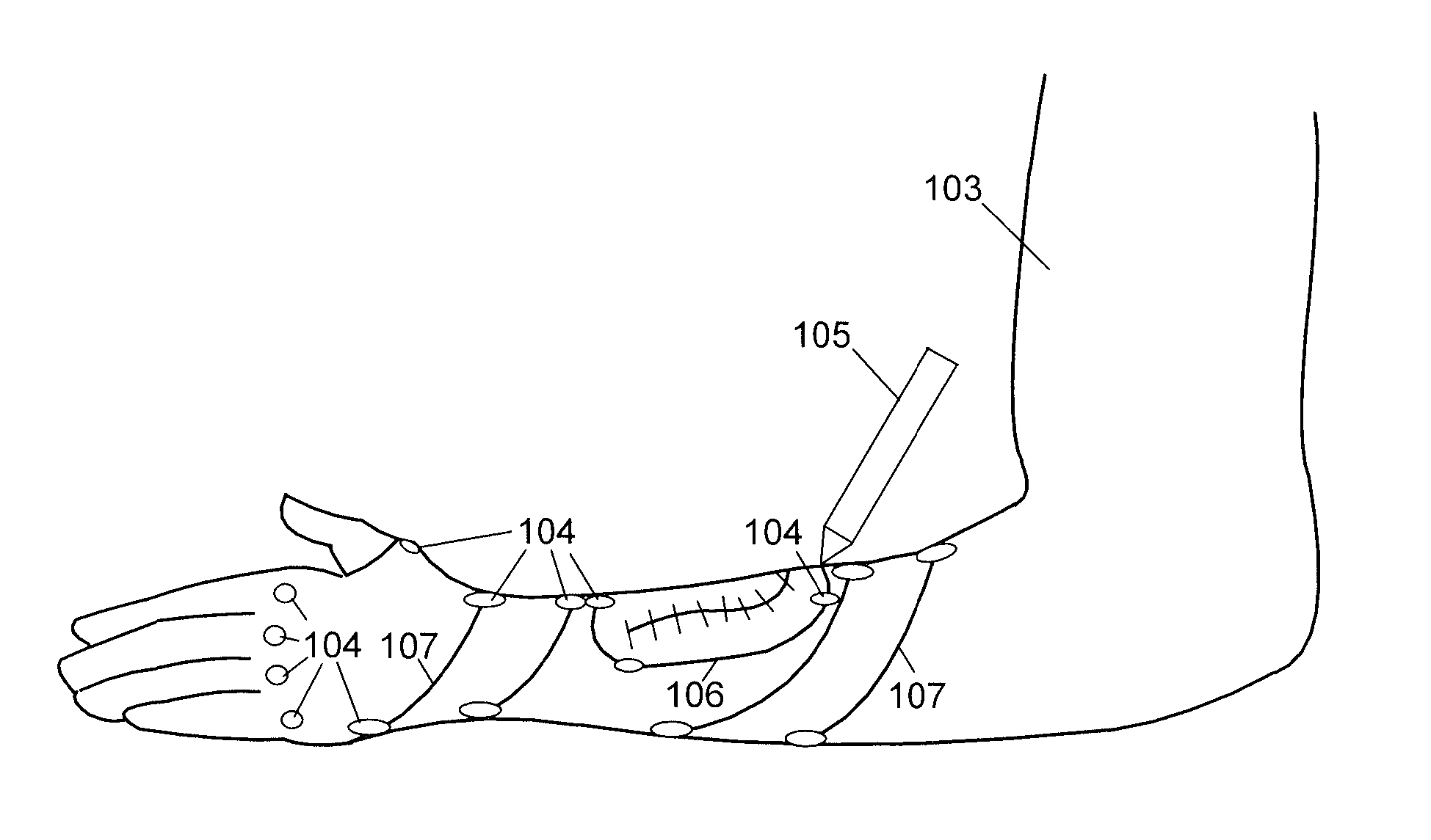
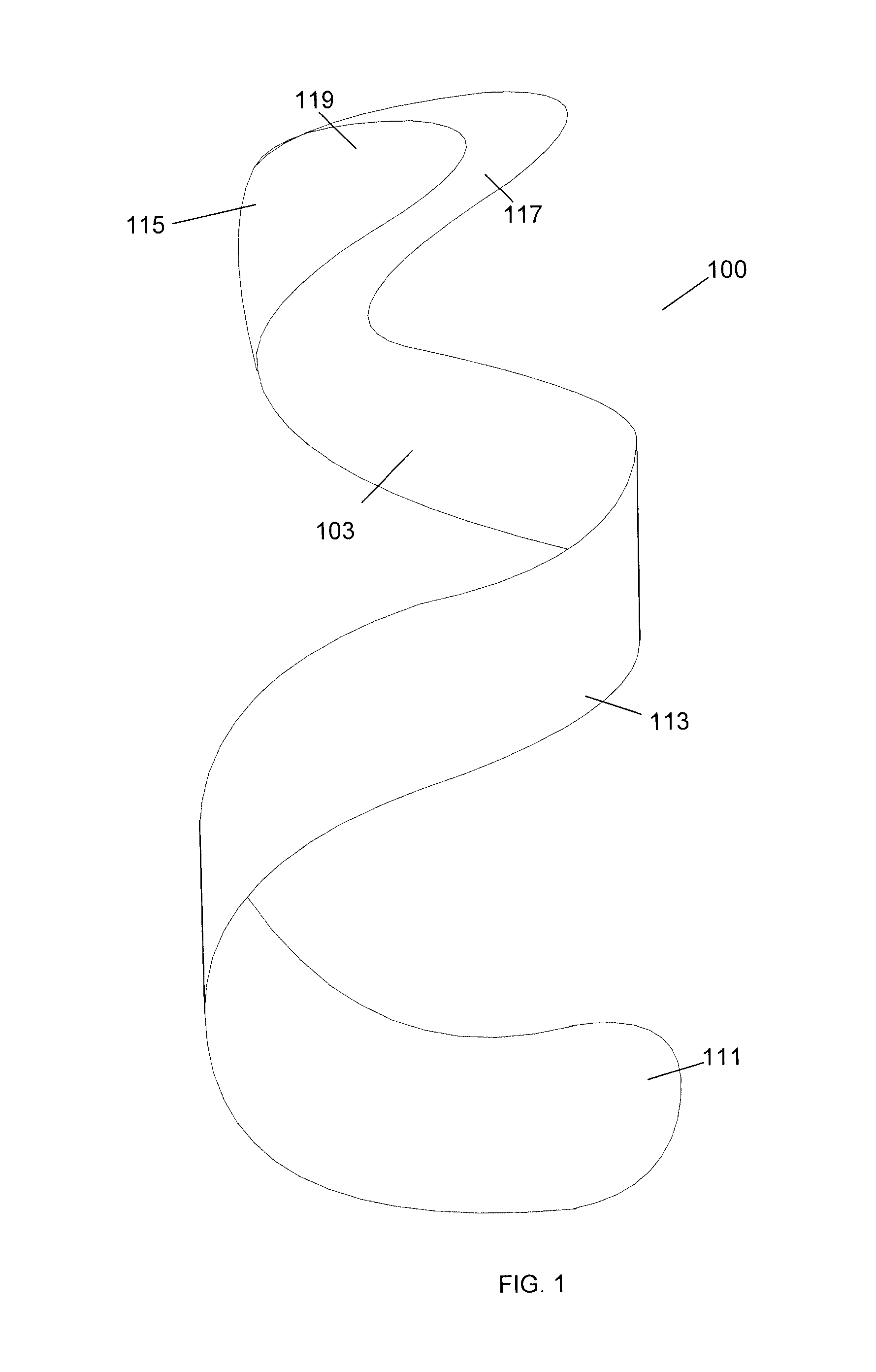
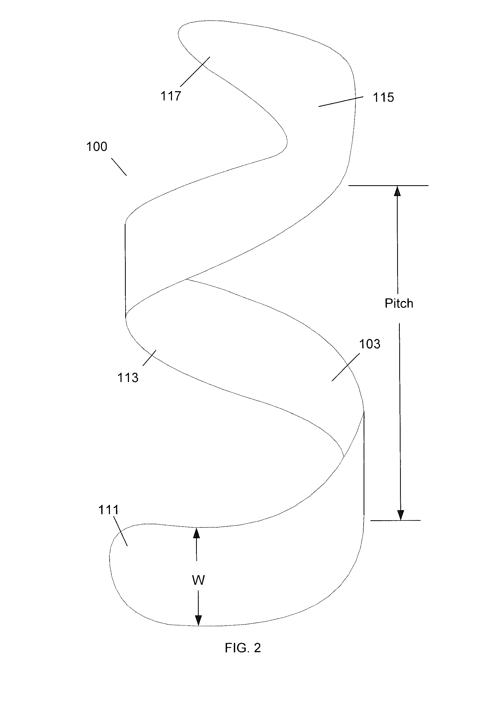
[0023]The present invention is a custom designed spiral brace. The term “spiral” is used to describe the three dimensional curve of a brace that wraps at least one full circumferential turn around an axis of the limb in a generally helical shape. The spiral brace can also have interior surfaces that correspond closely to a digital representation of a portion of a patient's body which can be from an optical scan or photograph(s) of the patient. When a patient injures a limb, the spiral brace can be designed to closely fit around the limb. In order to provide a close fit around the limb, the interior surfaces can be slightly larger than the digital representation of the portion of the patient's body. Thus, the interior surfaces are not an exact match but correspond to the digital representation of the patient's body. The inventive spiral brace can be designed to resist specific types of movement. For example, a spiral brace can be an arm brace that allows movement of the fingers and t...


PUM


Abstract

A spiral brace has an inner surface that corresponds to a digital representation of an injured limb. The spiral brace can wrap around a length of the limb in a helical manner. The body of the spiral brace may be a single piece structure that is fenestrated to provide air circulation to the injured limb.

Description

CROSS REFERENCE TO RELATED APPLICATIONS[0001]This application claims priority to U.S. Provisional Patent Application No. 61 / 720,861, “Spiral Brace” filed Oct. 31, 2012 and is a continuation-in-part of PCT Patent Application No. PCT / US2012 / 051612, “Adjustable Brace” filed Aug. 20, 2012 which claims priority to U.S. patent application Ser. No. 13 / 214,096, “Adjustable Brace” filed Aug. 19, 2011 which is a continuation-in-part of U.S. patent application Ser. No. 12 / 820,968, “Modular Custom Braces, Casts And Devices And Methods For Designing And Fabricating” filed Jun. 22, 2010 which is a continuation-in-part of U.S. patent application Ser. No. 12 / 615,196, now U.S. Pat. No. 8,005,651, “Custom Braces, Casts and Devices And Methods For Designing And Fabricating” filed Nov. 9, 2009 which claims priority to U.S. Provisional Patent Application No. 61 / 112,751, “Brace And Cast” filed on Nov. 9, 2008, U.S. Provisional Patent Application No. 61 / 168,183, “Orthopedic Braces” filed in Apr. 9, 2009, ...

Claims


Application Information

Patent Timeline
IPC IPC(8): A61F5/01
CPCA61F5/013A61F5/0118B33Y80/00A61H2003/006A61H3/02
Inventor SUMMIT, SCOTTTRAUNER, KENNETH B.
Owner 3D SYST INC
Why Eureka
Try Eureka