
Wireless communication network for control of industrial equipment in harsh environments

a technology of industrial equipment and wireless communication technology, applied in the field of communication between industrial equipment, can solve the problems of exacerbating the problem of extending cables to these remote welding locations, affecting the safety of workers, so as to facilitate wireless communication and facilitate communication

Active Publication Date: 2014-02-20
ILLINOIS TOOL WORKS INC
View PDF19 Cites 62 Cited by
  • Summary
  • Abstract
  • Description
  • Claims
  • Application Information

AI Technical Summary

Benefits of technology

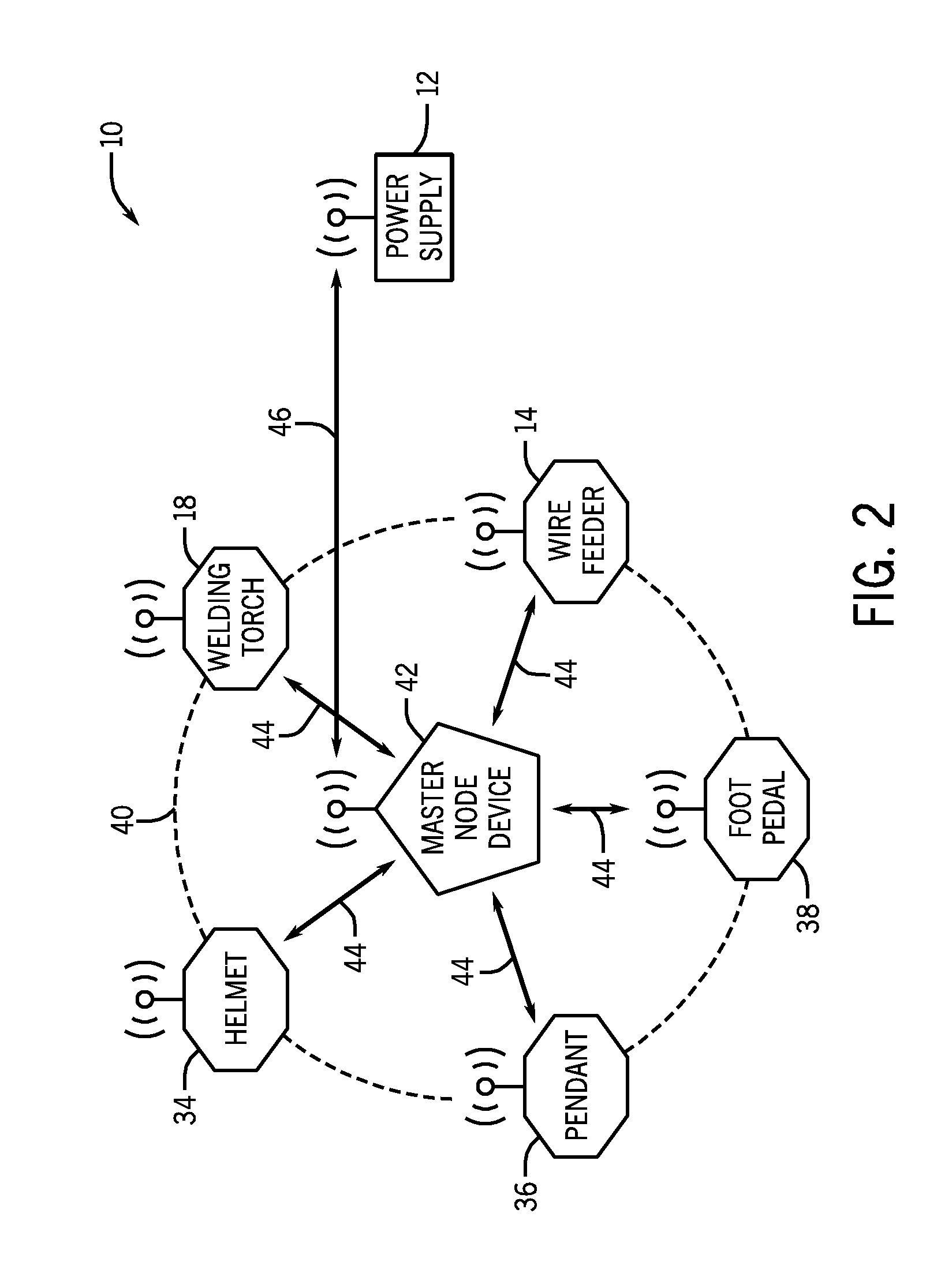
The present invention relates to a wireless communication network for control of industrial equipment in harsh environments. The invention addresses the problem of long cables and noise interference in such environments, and the difficulty of using wireless communication technologies in such environments. The invention provides a solution by incorporating a master node device that facilitates communication with a welding power supply unit via a long-range communication link, and wirelessly communicating between one or more welding-related devices and the master node device via a short-range wireless communication network. The wireless communication network includes one or more welding-related devices such as welding wire feeders, welding torches, welding helmets, welding pendants, and welding foot pedals. The invention allows for seamless communication with the welding equipment and accessories, and provides better control and efficiency in industrial environments.

Problems solved by technology

As such, long cables are often extended to such remote welding locations, which can become very cumbersome.
Moreover, in certain welding applications, such as ship building applications, a number of remote welding locations may be used at any given time in relatively small areas, thereby exacerbating the problem of extending cables to these remote welding locations.
Furthermore, the use of wireless communication technologies in such environments has heretofore proven problematic, at least due to noise considerations (which generally hamper wireless communication), security considerations, and so forth.

Method used


Image

  • Wireless communication network for control of industrial equipment in harsh environments
  • Wireless communication network for control of industrial equipment in harsh environments
  • Wireless communication network for control of industrial equipment in harsh environments

Examples


Embodiment Construction

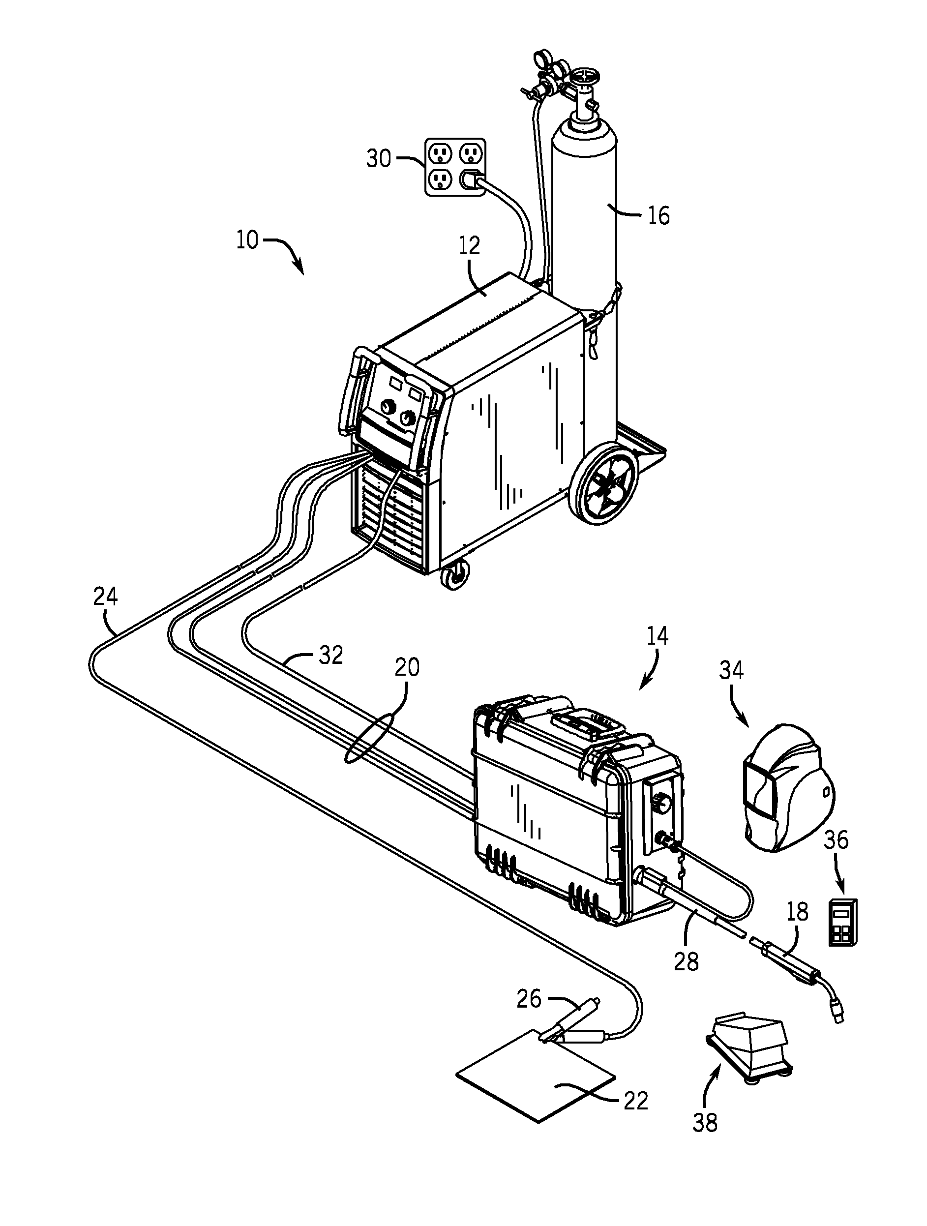
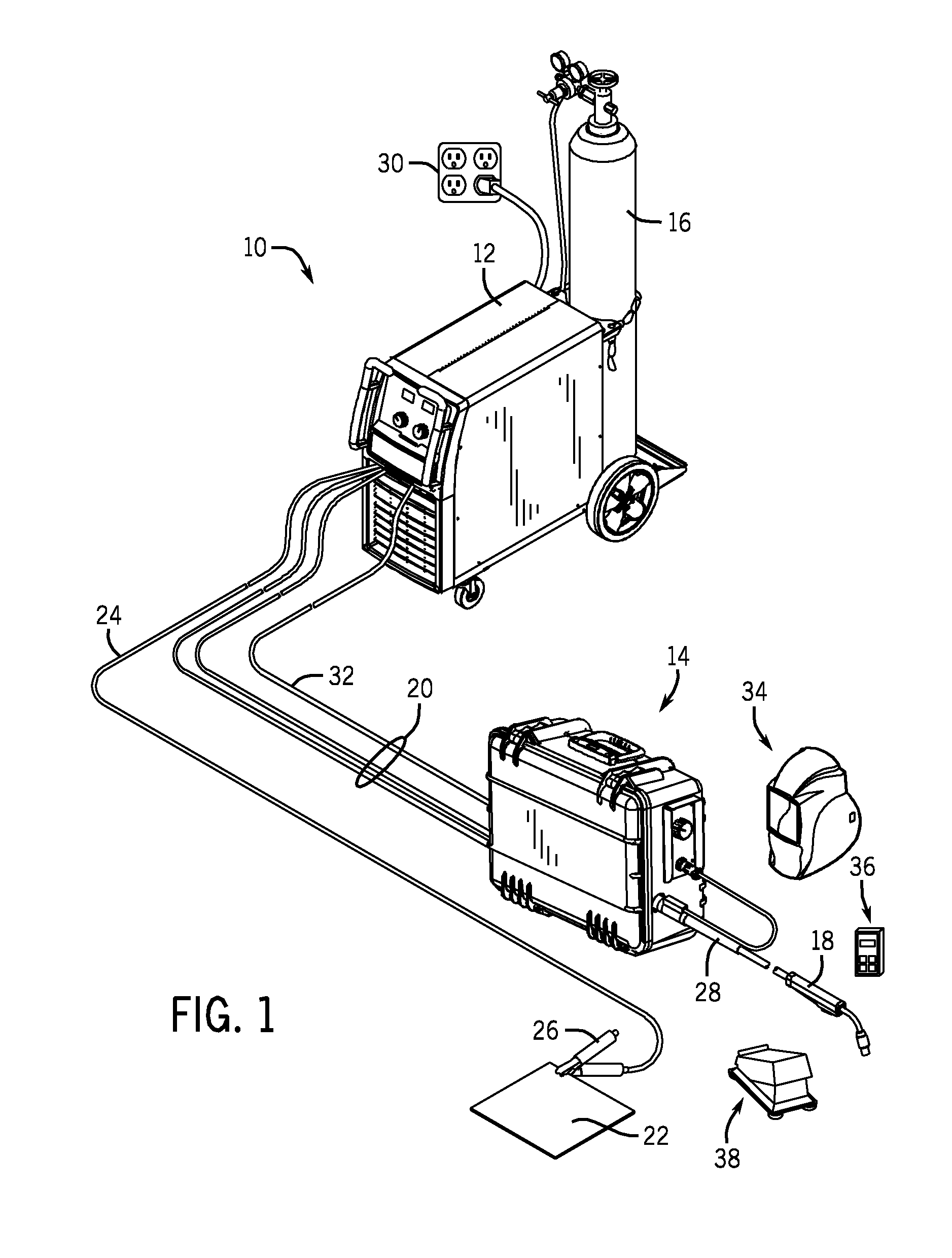
[0018]Turning to the figures, FIG. 1 is a diagram of an embodiment of a welding system 10 that may utilize wireless communication networking techniques, in accordance with embodiments of the present disclosure. It should be appreciated that, while the welding system 10 described herein is specifically presented as a gas metal arc welding (GMAW) system 10, the presently disclosed wireless communication networking techniques may also be used with other arc welding processes (e.g., FCAW, FCAW-G, GTAW, SAW, SMAW, or similar arc welding processes). More specifically, as described in greater detail below, all equipment and accessories used in the welding system 10 may be configured to wirelessly communicate with each other, as well as communicate with centralized or distributed welding control systems. The welding system 10 includes a welding power supply unit 12, a welding wire feeder 14, a gas supply system 16, and a welding torch 18. The welding power supply unit 12 generally supplies ...


PUM

PropertyMeasurementUnit
distanceaaaaaaaaaa
distanceaaaaaaaaaa
distanceaaaaaaaaaa

Abstract

In certain embodiments, a system includes a master node device. The master node device includes communication circuitry configured to facilitate communication with a welding power supply unit via a long-range communication link, and to facilitate wireless communication with one or more welding-related devices via a short-range wireless communication network.

Description

CROSS REFERENCE TO RELATED APPLICATIONS[0001]This application is a Non provisional U.S. patent application of U.S. Provisional Patent Application No. 61 / 684,497, entitled “Wireless Communication Network for Control of Industrial Equipment in Harsh Environments”, filed Aug. 17, 2012, which is incorporated herein by reference in its entirety.BACKGROUND[0002]The invention relates generally to communications between industrial equipment and, more specifically, to a wireless communication network for control of industrial equipment in harsh environments.[0003]Welding-related devices, such as the welding wire feeders, welding torches, welding helmets, welding control pendants, welding foot pedals, and so forth, are often operated at welding locations that are remote from sources of power, such as welding power supply units. For example, such remote welding locations may be up to, or even greater than, 300 feet from a source of power. As such, long cables are often extended to such remote ...

Claims


Application Information

Patent Timeline
Patent Type & Authority Applications(United States)
IPC IPC(8): B23K9/095H04W4/02H04W4/70H04W4/80
CPCB23K9/0953H04W4/70H04W4/80B23K9/1087H04W4/02B23K9/124
Inventor DINA, DANIELDOWNIE, KATHY LEE
Owner ILLINOIS TOOL WORKS INC
Learn More