Engine control using an asynchronous data bus

a data bus and control system technology, applied in the direction of data switching network, electric control, ignition automatic control, etc., can solve the problems of increasing complexity, reducing the efficiency of the engine, so as to achieve the effect of superior aesthetic appeal

Inactive Publication Date: 2014-02-13
MSD LLC
View PDF11 Cites 16 Cited by
  • Summary
  • Abstract
  • Description
  • Claims
  • Application Information

AI Technical Summary

Benefits of technology

The invention provides a decentralized engine control unit (ECU) that is easy to install and maintain. It eliminates the need for a timing signal to ensure synchronicity and achieves this through the use of the CAN messaging system and time stamp capabilities. The main ECU sends two timing messages to remote modules, which compare the time stamps and use the difference to synchronize their own time base with the main ECU. The technical effects of the invention include improved aesthetic appeal and simplified installation maintenance diagnostics.

Problems solved by technology

Variations in atmospheric temperature and pressure, engine temperature, load and speed make perfect carburetion nearly impossible to obtain under all driving conditions.
Accordingly, retrofitting a carbureted engine with a modern port or direct injection system always comes at the expense of increased complexity.
However, difficulty in minimizing the number of conductors in the ECU harness stems from the fact that ignition and injector sequence timing must be precisely and accurately controlled in relation to the crankshaft position in real time.
Although such existing automotive buses are ideal for connecting ECUs to various sensors, they are ill-suited for engine ignition and injection control, because they are non-deterministic in nature, having unpredictable propagation times. According to conventional design logic, therefore, a engine control bus in decentralized ECU would be a dedicated real-time bus with discrete point-to-point connections.

Method used


Image

  • Engine control using an asynchronous data bus
  • Engine control using an asynchronous data bus
  • Engine control using an asynchronous data bus

Examples


Embodiment Construction

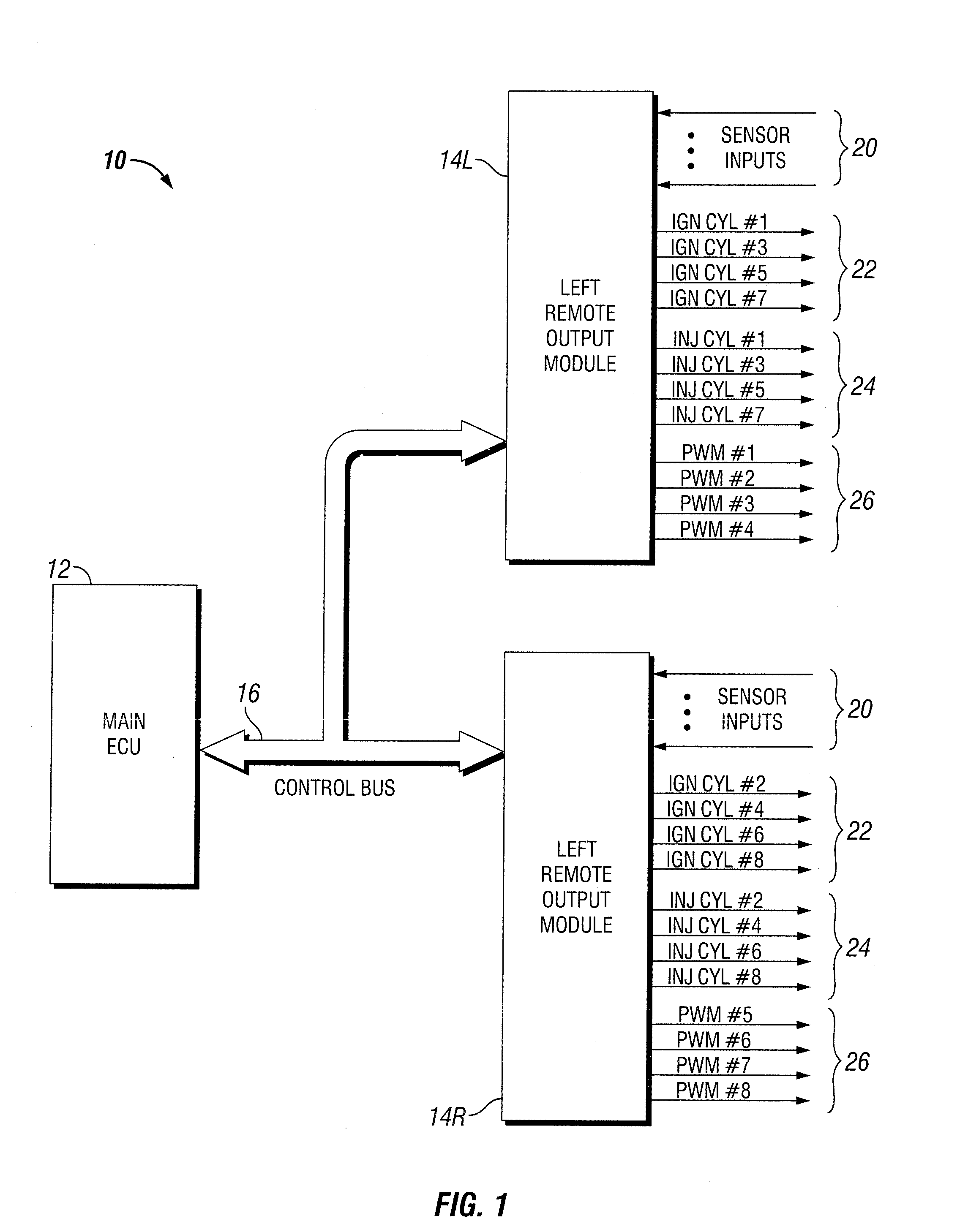
[0029]A decentralized EFI ECU system 10 with distributed processing for a V-8 engine is shown in FIG. 1. System 10 includes a main ECU module 12 and left and right bank remote input / output modules 14L, 14R. Each remote module includes one or more input channels 20 for sensor inputs, four ignition outputs 22, and four fuel injector outputs 24. Additionally, each remote module may optionally include a number of pulse width modulation (PWM) outputs 26, which may be used for electronic throttle control, variable valve timing, or idle air motor actuation, for example. A bidirectional ECU control bus 16, as described below, operatively connects main ECU 12 to left and right bank remote modules 14L, 14R.

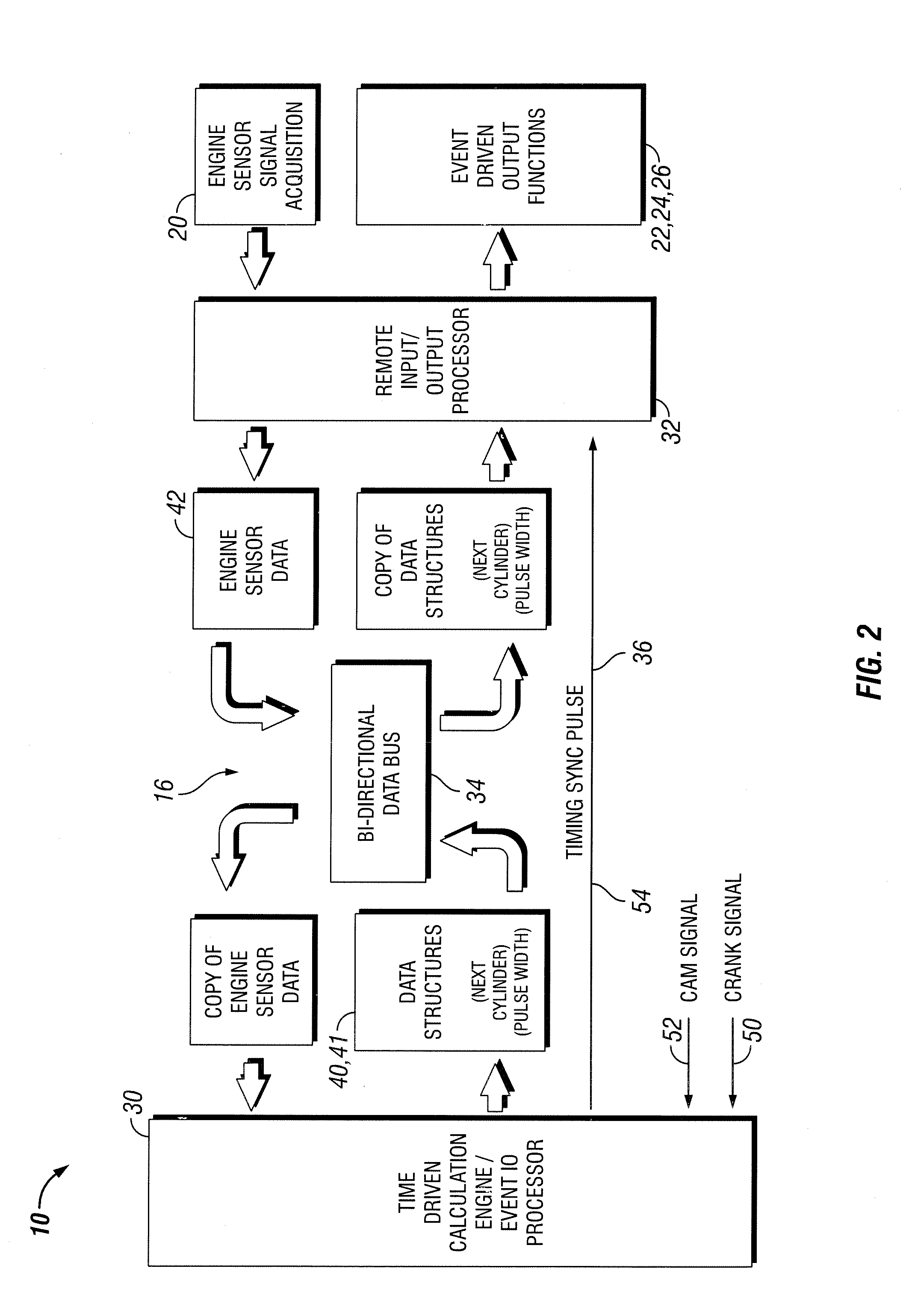
[0030]FIG. 2 illustrates the basic topology of the distributed ECU system 10. One or more remote processors 32 (of the left or right bank remote module 14L, 14R, for example) receive signals 20 from various engine sensors and encode the sensor data into various sensor data structures, or me...


PUM


Abstract

An engine control unit with distributed processing includes a main ECU and remote modules with sensor inputs and ignition and injector outputs. A bidirectional asynchronous CAN data bus and a square wave timing signal operatively connect the components. Synchronous ignition and ignition data and asynchronous sensor and control data are concurrently transmitted between components using CAN messaging. Synchronicity is accomplished using the timing signal. The rising edge of each pulse triggers dwell and injection start times, and the falling edge triggers ignition. Injection and dwell time values, the cylinders to dwell and fire, and the injectors to energize, are transmitted using CAN messaging. The remote modules process the control messages and timing signal and generate the appropriate ignition, injector, and pulse width modulation control signals. Alternatively, time stamp capabilities of the CAN bus topology are used for synchronization. The system and methodology simplify interconnection, using fewer wires and enhancing aesthetics.

Description

BACKGROUND OF THE INVENTION[0001]1. Field of the Invention[0002]This invention relates generally to engine control systems for internal combustion engines, and in particular to a control bus for communication between electronic engine control components.[0003]2. Background Art[0004]A carburetion fuel delivery system uses a carburetor to supply and meter the mixture of fuel and air in relation to the speed and load of the engine. Variations in atmospheric temperature and pressure, engine temperature, load and speed make perfect carburetion nearly impossible to obtain under all driving conditions. In contrast, fuel injection systems meter fuel much more precisely than carburetors, thereby allowing optimal fuel-air mixture to be more consistently delivered across the full spectrum of driving conditions. Fuel injection provides increased horsepower, higher torque, improved fuel economy, quicker cold starting, and other benefits. As a result, fuel injection systems have largely replaced ...

Claims


Application Information

Patent Timeline
Patent Type & Authority Applications(United States)
IPC IPC(8): F02D41/34F02D41/26
CPCF02D41/0082F02D41/009F02D41/266F02D41/28F02P5/1518F02P3/045H04L12/40058F02P5/045Y02T10/40
Inventor EISENBARTH, DARWIN SPENCERWITTKOPF, MICHAELGREENE, JEFFREY DAVIDLAVI, EITAN
Owner MSD LLC
Why Eureka
Try Eureka