
Total knee replacement substituting function of anterior cruciate ligament

a technology of anterior cruciate ligaments and knee replacements, applied in the field of prosthetic knees, can solve the problems of difficult to achieve with bearing surfaces alone, difficult to replicate the constraints provided by these ligaments, and more difficult to achieve. , to achieve the effect of reducing anterior-posterior displacement, enhancing the function of the basic design, and preventing excessive anterior displacement of the femur

Active Publication Date: 2014-02-13
NEW YORK UNIV
View PDF36 Cites 7 Cited by
  • Summary
  • Abstract
  • Description
  • Claims
  • Application Information

AI Technical Summary

Benefits of technology

The patent describes a new type of knee replacement that partially replaces the natural knee joint with a femoral and tibial bearing surface that work together to distribute the load across the joint. The design also includes intercondylar guiding surfaces on both components that can mimic the function of the anterior cruciate ligament. The design features a steep femoral surface that prevents excessive anterior displacement of the femur in flexion and a shallow maleuronical surface that induces posterior displacement in the second half of flexion. The design also allows for internal-external rotation of the femur without edge contacts or reduced anterior-posterior displacement on the medial side and increased anterior-posterior displacement on the lateral side. Overall, this new design provides more natural movement and reduced damage to the knee joint.

Problems solved by technology

While symmetric designs can use simply derived geometry for both the femoral and tibial surfaces, as well as for cams and posts, such an approach is more difficult if anatomic motion patterns are required.
For any type of design where both of the cruciates are resected, the problem of replicating the constraints provided by these ligaments remains a challenge to this day.
In particular, providing AP stability and rotational laxity throughout flexion, while inducing femoral rollback to achieve high flexion angles without posterior impingement, seems difficult to achieve with the bearing surfaces alone, even with a cam-post mechanism.
So far however, these designs do not replicate anatomic motion and laxity-stability characteristics, or have certain motion abnormalities in some patients.

Method used


Image

  • Total knee replacement substituting function of anterior cruciate ligament
  • Total knee replacement substituting function of anterior cruciate ligament
  • Total knee replacement substituting function of anterior cruciate ligament

Examples


Embodiment Construction

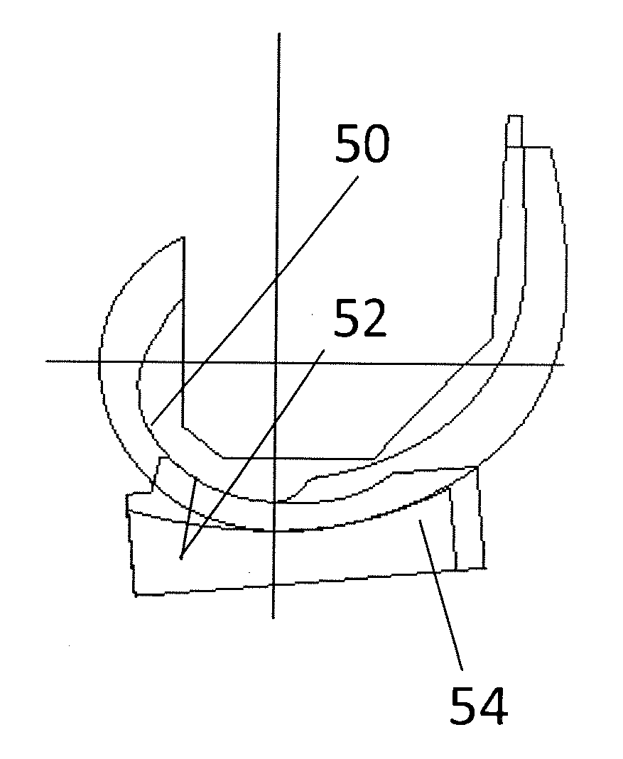
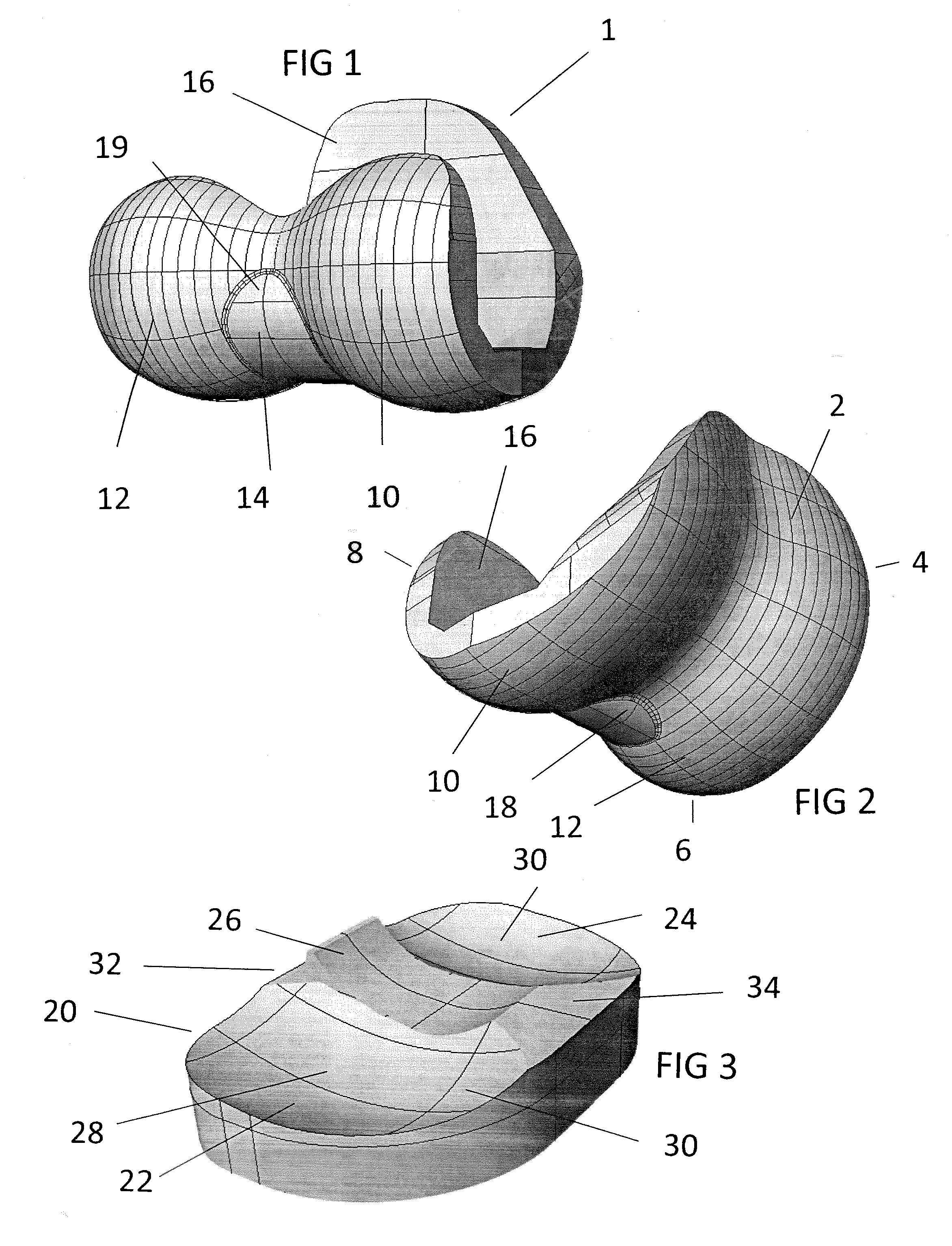
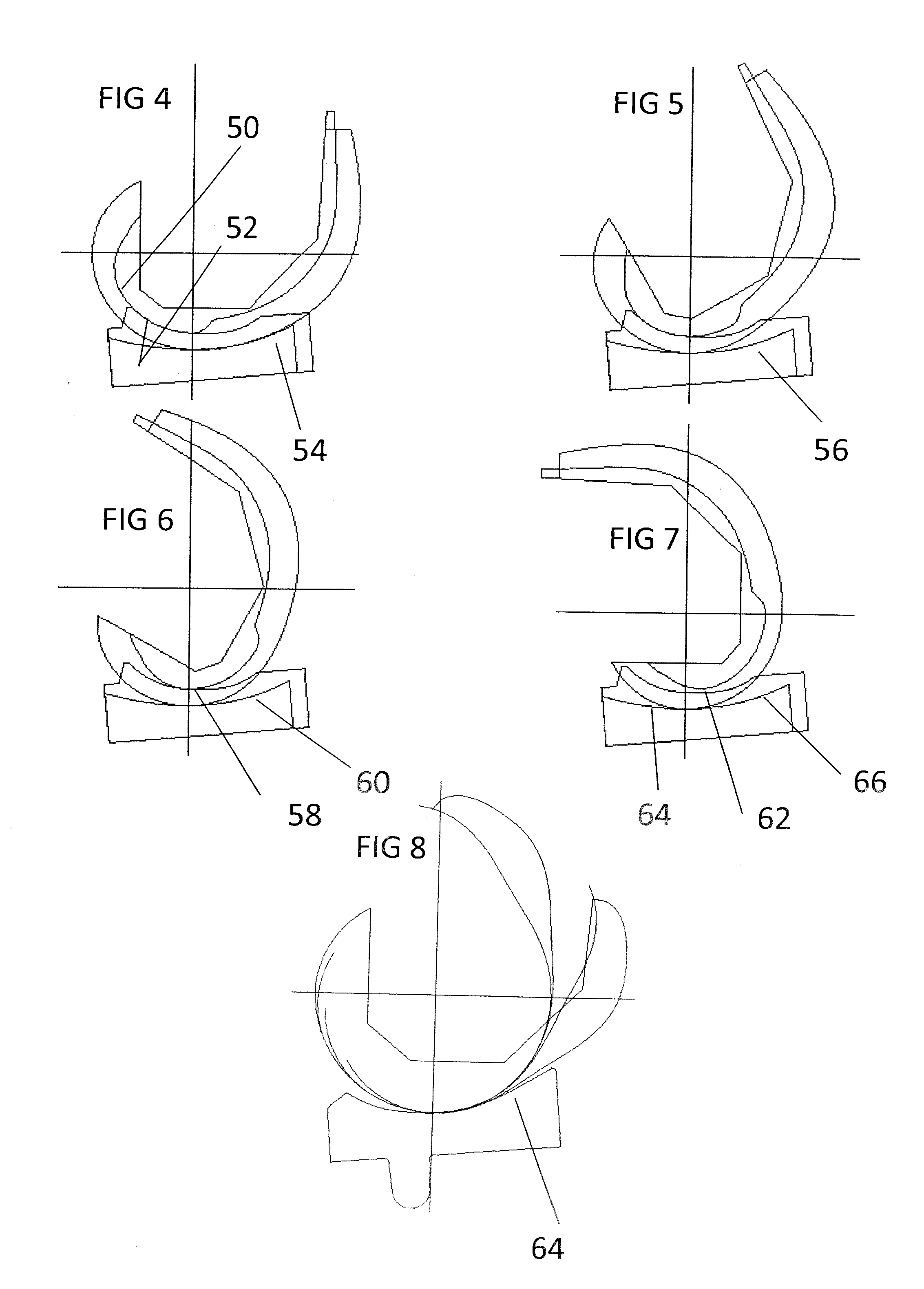
[0018]In an embodiment, as shown in FIGS. 1, 2, and 3, the femoral component 1 comprises an anterior portion 2, a distal portion 6, and a posterior portion 8. The anterior portion 2 is called the patella flange 4 along which the patella (not shown) slides during flexion-extension. The lateral femoral condyle 12 and the medial femoral condyle 10 are biconvex surfaces which locate against their corresponding tibial condylar bearing surfaces 24 and 22. The interior surface of the femoral component 16 comprises facets that are typically used to interface against the prepared surface of the distal femur. A femoral intercondylar bearing surface 14 is located between the femoral condyles 10 and 12 and extends from a distal location 18 to a posterior location 19. The outer radius of the femoral intercondylar bearing surface seen in the sagittal view, from the lateral or medial sides, is smaller than that of the lateral 12 and medial 10 femoral condyles. The distal region of the intercondyla...


PUM


Abstract

A total knee replacement prosthesis comprising condylar and intercondylar bearing surfaces configured to manage anterior / posterior displacement between the articulating femoral and tibial components.

Description

PRIORITY CLAIM TO PREVIOUS PATENT APPLICATION[0001]This U.S. utility patent application claims the benefit of U.S. Provisional Patent Application No. 61 / 681,465 that was filed on Aug. 9, 2012, the entire disclosure of which is incorporated by reference in its entirety. All references cited in this specification, and their references, are incorporated by reference herein where appropriate for teachings of additional or alternative details, features, and / or technical background.BACKGROUND OF THE INVENTION[0002]1. Field of the Invention[0003]The present invention generally relates to prosthetic knee where the femoral and tibial components comprise condylar and intercondylar bearing surfaces that provide management of anterior-posterior displacement throughout the full flexure range.[0004]2. Description of the Related Art[0005]The first condylar replacement type of total knee replacement intended for cruciate resection was the Freeman-Swanson (Freeman, Swanson, Todd 1977), designed in t...

Claims


Application Information

Patent Timeline
Patent Type & Authority Applications(United States)
IPC IPC(8): A61F2/38
CPCA61F2/3886A61F2/38A61F2002/30934A61F2/3859A61F2/389A61F2002/30935
Inventor WALKER, PETER STANLEY
Owner NEW YORK UNIV
Learn More