
Integrated Retainer and Seal for Coaxial Cable Connector

a technology of retainer and coaxial cable, which is applied in the direction of coupling device connection, dustproof/splashproof/drip-proof/waterproof/flameproof connection, coupling device details, etc., can solve the problem that the quality of the electrical connection can either positively or negatively affect the resulting electric signal as well as the performance of the connector, and the environmental seal negatively affects the electric signal between the cable and the connector

Inactive Publication Date: 2014-02-13
JOHN MEZZALINGUA ASSOC LLC
View PDF0 Cites 25 Cited by
  • Summary
  • Abstract
  • Description
  • Claims
  • Application Information

AI Technical Summary

Benefits of technology

This invention relates to connectors for coaxial cables, especially connectors that have a center conductor. The patent describes a seal member that can be used with a connector to provide a seal when the cable is fully inserted. The invention also includes a coaxial cable connector that has a clamp and a cable seal, which forms an environmental seal between the connector and the cable. The technical effect of this invention is to improve the reliability and performance of coaxial cable connectors in a robust and efficient way.

Problems solved by technology

Indeed, the quality of the electrical connection can either positively or negatively impact the resulting electric signal as well as the performance of the connector.
One issue that negatively impacts the electric signal between the cable and the connector is the environmental seal.
Currently, variations in the corrugation dimensions of the manufactured cable can lead to poor sealing between the connector and the outer conductor of the cable.
Improperly-sized connectors will negatively impact the environmental seal between the cable and the connector, resulting in moisture migration and extremely low performance.

Method used


Image

  • Integrated Retainer and Seal for Coaxial Cable Connector
  • Integrated Retainer and Seal for Coaxial Cable Connector
  • Integrated Retainer and Seal for Coaxial Cable Connector

Examples


Embodiment Construction

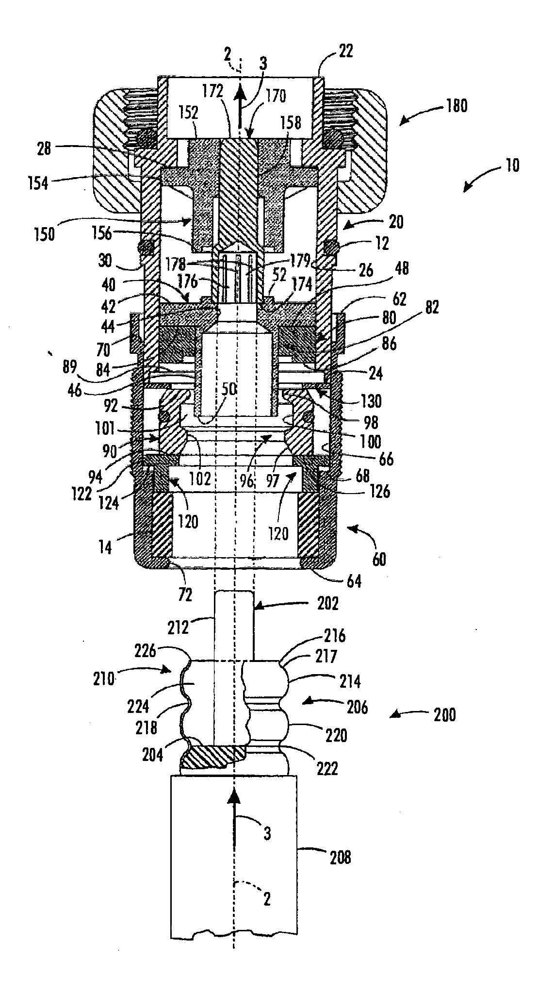
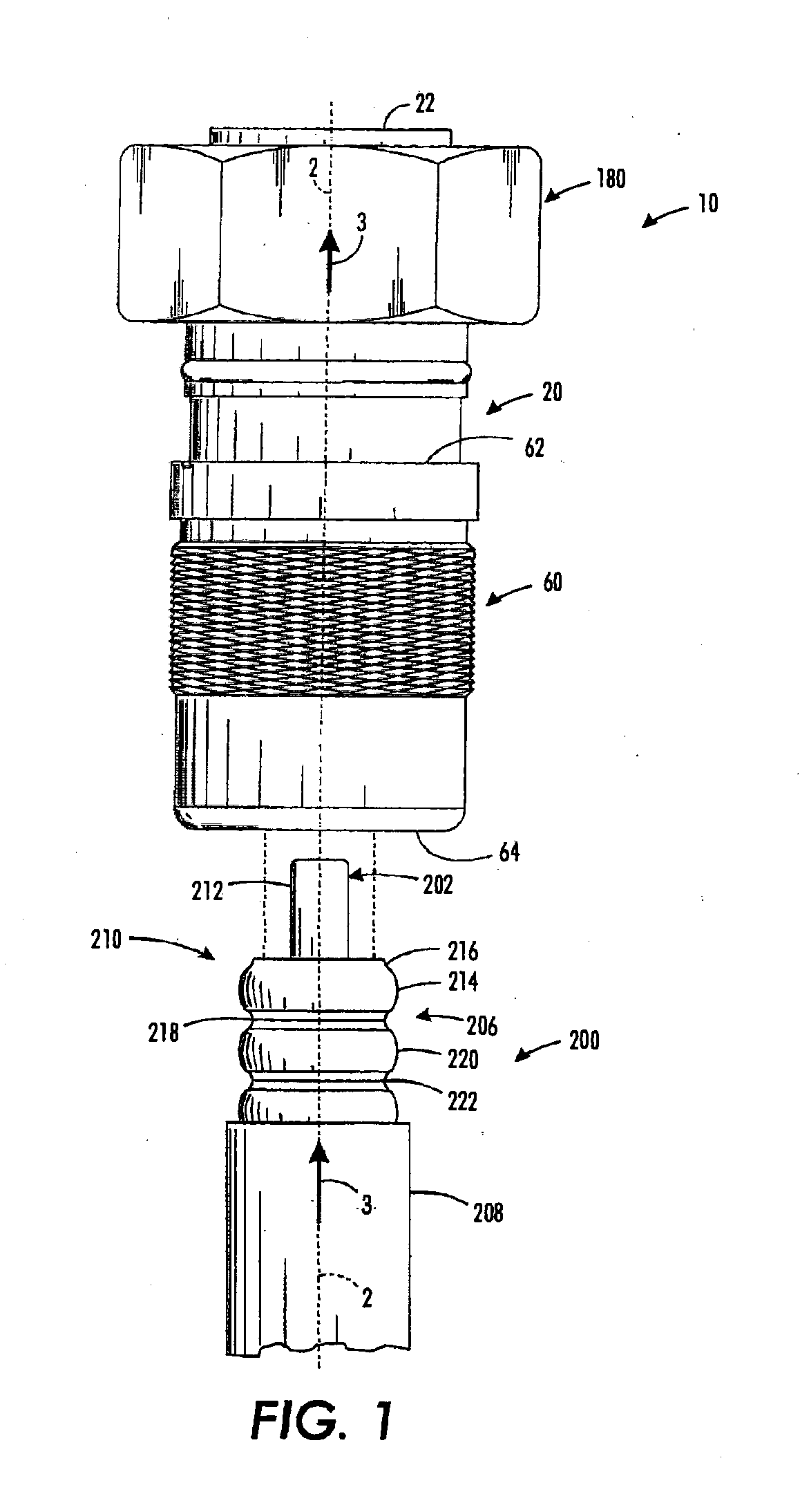
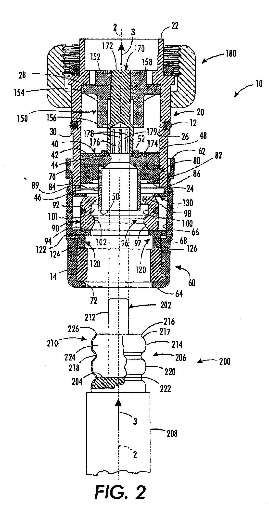
[0041]Referring first to FIGS. 1 and 2, one embodiment of the connector 10 and an annularly corrugated coaxial cable 200 with a prepared end 210 are shown aligned on a common central axis 2. Since the connector 10 and the annularly corrugated coaxial cable 200 are generally axially symmetric about their central axis 2, the “radially outward” direction in the following description is considered to be outwardly away from the central axis 2. Conversely, “radially inward” with respect to connector component motion is considered to be inwardly toward the central axis 2. Moreover, “axial advancement” of the cable 200 with respect to the connector 10 and “axial advancement” of components of the connector 10 with respect to one another is considered to be along the length of the axis 2.

[0042]The coaxial cable 200 that may be coupled to the connector of the one embodiment is comprised of a solid center conductor 202 surrounded by an insulator 204, a corrugated outer conductor 206 surrounding...


PUM

PropertyMeasurementUnit
angleaaaaaaaaaa
angleaaaaaaaaaa
angleaaaaaaaaaa

Abstract

A coaxial cable connector including a connector body, a compression member axially movable with respect to the connector body, a clamp having a cable end, a terminal end, and an inner bore, the inner bore having a contact surface configured to contact an outer conductor of a coaxial cable, the cable end having a slot extending toward the terminal end, and a cable seal having a band, a link, and an engagement member, the band located adjacent the contact surface, the link configured to fit into the slot, and the engagement member attached to the link opposite the band, the engagement member located adjacent the clamp, wherein the engagement member provides radially inward pressure, and wherein, upon assembly to the coaxial cable, the band forms an environmental seal between the contact surface and the outer conductor of the coaxial cable is provided. An associated method is further provided.

Description

CROSS-REFERENCE TO RELATED APPLICATIONS[0001]This application claims the benefit of and priority to U.S. Provisional Application No. 61 / 682,711, filed Aug. 13, 2012, and entitled, “Integrated Retainer and Seal for Coaxial Cable Connector.”FIELD OF TECHNOLOGY[0002]This following relates generally to the field of coaxial cable connectors and more particularly to a connector assembly for use with coaxial cables having an annular corrugated outer conductor.BACKGROUND[0003]Corrugated coaxial cables are electrical cables that are used as transmission lines for radio frequency signals. Coaxial cables are composed of an inner conductor surrounded by a flexible insulating layer, which in turn is surrounded by a corrugated outer conductor that acts as a conducting shield. An outer protective sheath or jacket surrounds the corrugated outer conductor.[0004]A corrugated coaxial cable in an operational state typically has a connector affixed on either end of the cable. The quality of the electric...

Claims


Application Information

Patent Timeline
Patent Type & Authority Applications(United States)
IPC IPC(8): H01R13/52H01R43/00
CPCH01R43/005H01R13/5221H01R13/5205H01R13/5219H01R24/564Y10T29/49174
Inventor NUGENT, ADAM T.
Owner JOHN MEZZALINGUA ASSOC LLC
Learn More