
Control mechanism for drawer slide assembly

a control mechanism and slide technology, applied in the field of slide assemblies, can solve the problems of lack of any kind of control over the movement of the drawer, the drawer, the cabinet, and the front of the drawer facia cover, and achieve the effects of reducing noise, limiting linear movement, and reducing nois

Inactive Publication Date: 2014-02-13
GRASS AMERICA
View PDF13 Cites 2 Cited by
  • Summary
  • Abstract
  • Description
  • Claims
  • Application Information

AI Technical Summary

Benefits of technology

The present invention is a control mechanism for a drawer slide assembly that prevents damage and noise by inhibiting forceful movement of the drawn relative to the cabinet housing. The mechanism comprises a drawer latch bracket and a shock-absorbing sub-assembly. The shock-absorbing sub-assembly includes an elongate bracket member associated with the cabinet rail, a movable latch associated with the elongate bracket member, and a shock absorber unit associated with the elongate bracket member for damping movement of the movable latch during a closing stroke of the drawer. This results in reduced noise and prevents damage to the assembly.

Problems solved by technology

The problem with such drawer slide assemblies, however, is that they lack means for providing any sort of control over the movement of the drawer as it closes in the cabinet housing.
As such, the drawer, cabinet, or a facia cover associated with the front of the drawer, can be damaged as the drawer is forcibly closed into the cabinet housing.
Such forceful movement of the drawer relative to the cabinet housing can also cause loud slamming noises upon impact between the drawer and the cabinet interface, and there can be damage to the associated drawer slide assembly mechanisms and rails, or the contents of the drawers themselves.

Method used


Image

  • Control mechanism for drawer slide assembly
  • Control mechanism for drawer slide assembly
  • Control mechanism for drawer slide assembly

Examples


Embodiment Construction

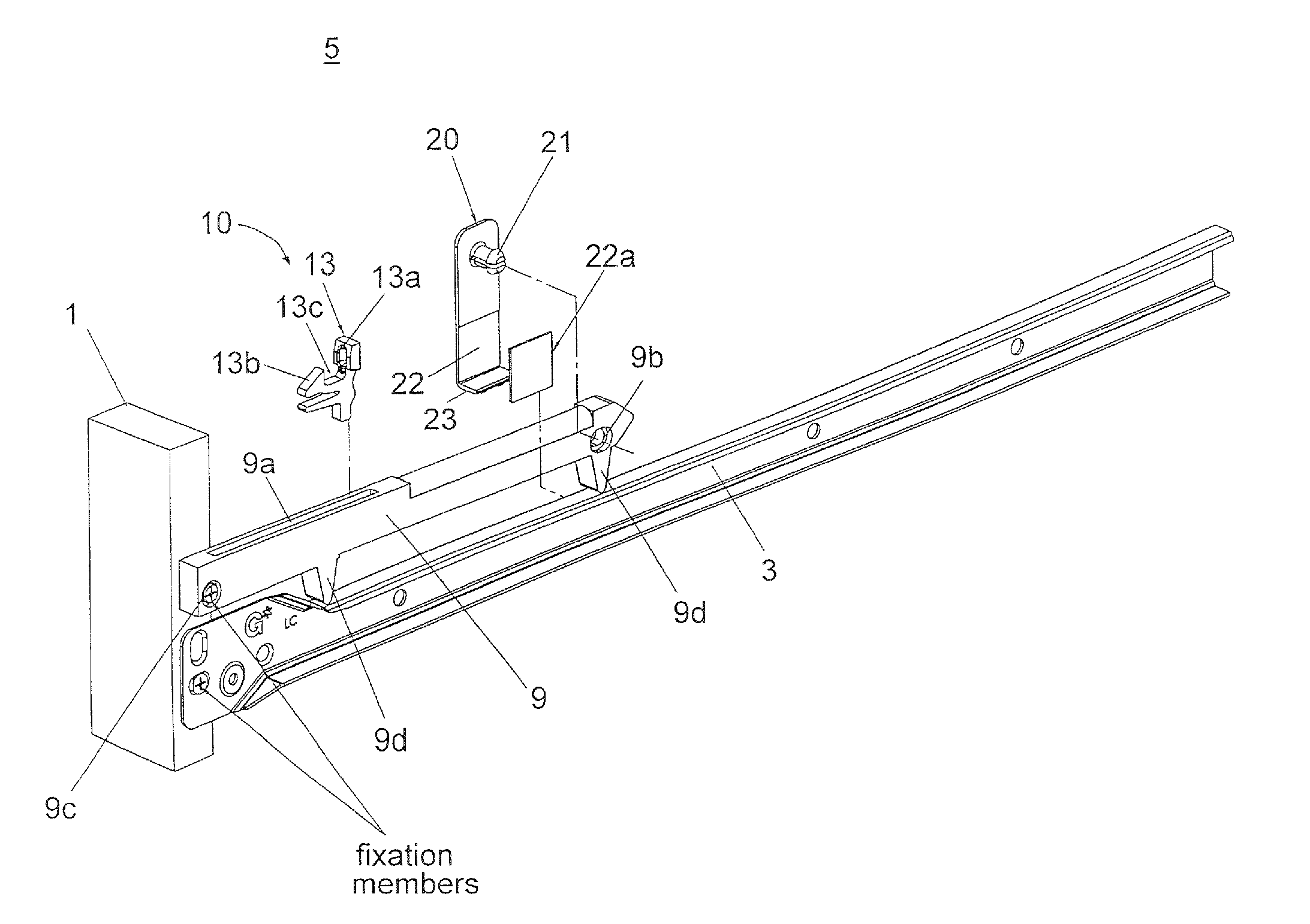
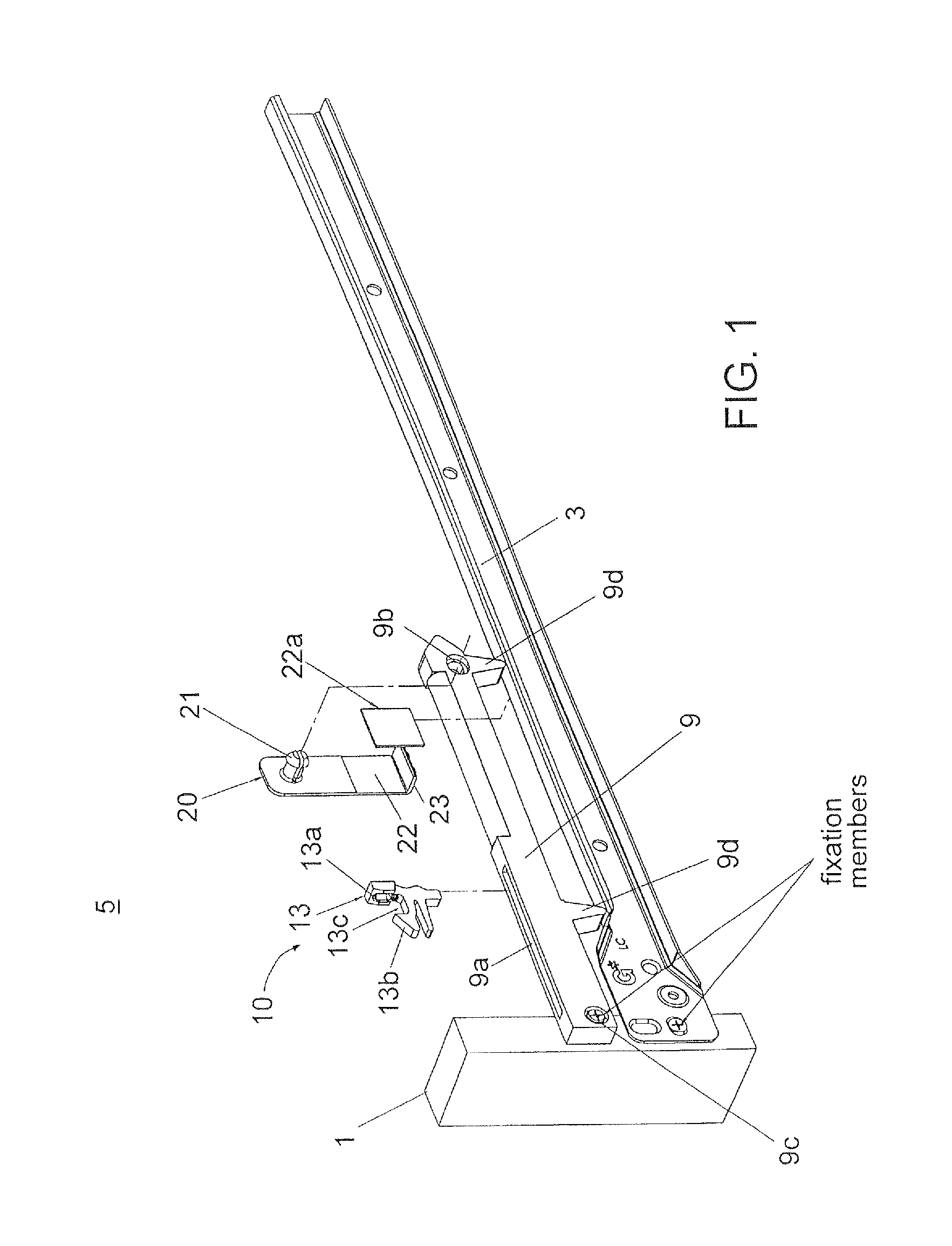
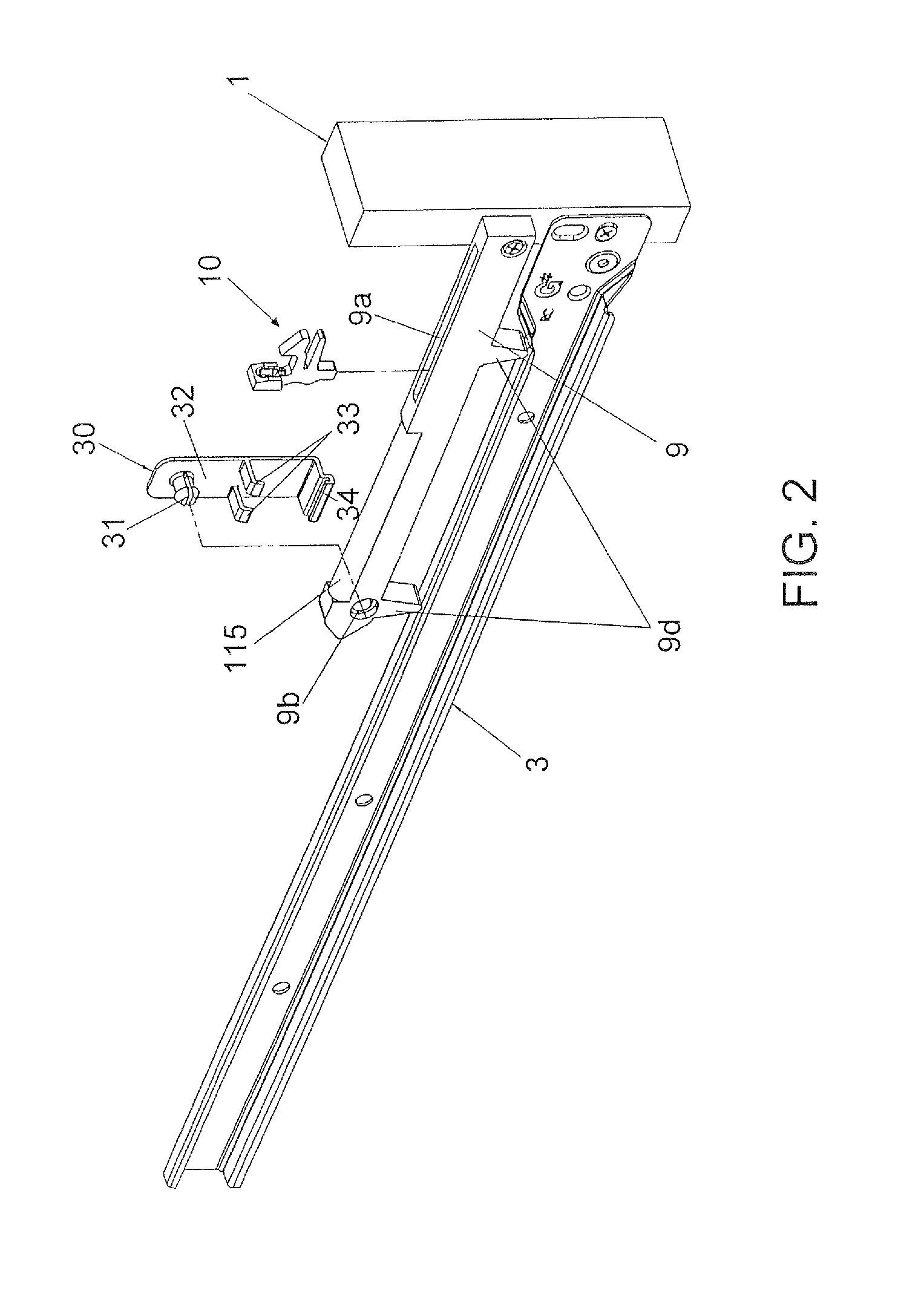
[0023]FIG. 1 is a perspective, left-side view of a drawer slide control mechanism 5 according to one embodiment on the present invention including a shock-absorbing sub-assembly and a combined stabilization bracket 20 for left and right cabinet rail attachment according to one aspect of the present invention (the drawer and drawer rail are removed).

[0024]The control mechanism according to the present invention is designed to function in a similar manner to that which is described in U.S. patent application Ser. No. 13 / 011,269, the entirety of which is incorporated herein by reference. In particular, many of the details of the internal mechanisms and functions that are described in connection with the shock absorbing sub-assembly in the '269 Application are the same in the present invention, and repetitious details are omitted. There are, however, some clear structural differences between the drawer control mechanism of the present invention and that described in the '269 Application...


PUM


Abstract

A control mechanism for a drawer slide assembly including a cabinet rail and a drawer rail is provided. The control mechanism comprises a latch bracket positioned on a portion of a drawer and having a post extending therefrom, a movable latch associated with the cabinet rail and capable of limited linear movement along a portion of the cabinet rail, the movable latch cooperating and engaging with the post of the latch bracket so as to move along with movement of the drawer when engaged with the post, and a damping mechanism for damping movement of the movable latch at least when the drawer is moving from an open position to a closed position.

Description

FIELD OF THE INVENTION[0001]The present invention relates generally to slide assemblies used in connecting drawers to cabinets, and more particularly relates to a control mechanism to dampen the movement of a drawer slide assembly as it is closed within the cabinet housing.BACKGROUND OF THE INVENTION[0002]Drawer slide assemblies are used in most drawer-cabinet settings to facilitate a smooth opening and closing of a drawer relative to the cabinet housing. The problem with such drawer slide assemblies, however, is that they lack means for providing any sort of control over the movement of the drawer as it closes in the cabinet housing. As such, the drawer, cabinet, or a facia cover associated with the front of the drawer, can be damaged as the drawer is forcibly closed into the cabinet housing.[0003]Such forceful movement of the drawer relative to the cabinet housing can also cause loud slamming noises upon impact between the drawer and the cabinet interface, and there can be damage ...

Claims


Application Information

Patent Timeline
Patent Type & Authority Applications(United States)
IPC IPC(8): A47B88/16A47B88/12
CPCA47B2210/0091A47B88/483
Inventor DOMENIG, GEORGPEER, MANFREDJIANG, CHENG
Owner GRASS AMERICA
Learn More