
Roller board with one or more user-maneuverable trucks and north-seeking return mechanism

a technology of roller boards and return mechanisms, which is applied in the direction of steering devices, bicycles, cycle equipments, etc., can solve the problems of affecting the reliable operation and the device requires more balance and coordination than many users can muster, so as to improve the reliability of the rotation assembly, increase the compression load, and reduce the length of the spring

Active Publication Date: 2020-12-08
ROLL INC
View PDF29 Cites 1 Cited by
  • Summary
  • Abstract
  • Description
  • Claims
  • Application Information

AI Technical Summary

Benefits of technology

Enhances maneuverability and stability, allowing for precise control during tricks and reducing the risk of wipeouts by automatically returning axles to a stable position, improving the confidence and safety of both novice and experienced riders.

Problems solved by technology

This action requires balance and coordination by the user and can provide challenges to a beginner or novice rider.
Once content with two-dimensional freestyle tricks such as wheelies, manuals, and pivots, popular skateboard tricks have become more complicated, three-dimensional, aerial maneuvers.
But this device requires more balance and coordination then many users can muster.
While convenient for a user riding along a street or sidewalk for recreation, this steering shaft can interfere with aerial trick maneuvers.
It can also provide a safety hazard to the user.
A compression spring connected between this disc and the bottom of the chassis of the wagon further limits the degree to which the front axle may be turned upon impact with an impediment, and biases the front wheels to their centered position.
However, the limited ability of the compression spring to pull the front axle back to its “true center” position is acceptable, because the user may easily use the handle bar to steer the wagon.
Thus, the skateboard according to Cooney does not provide the kind of maneuverability required for tricks.
However, the user's right foot is positioned above the left foot which can throw off balance.
Moreover, the large circular platform extends from the rear end of the skateboard, which interferes with the downward stomp exerted by users on the rear end of the board necessary for executing jump tricks.
It is also difficult for the user to control the maneuverability of the rear axle assembly given the simple nature of the mechanism, nor does the axle assembly return to its true forward-facing position on its own.
When the user releases the rotational force applied to the steering platform, the torsion spring “tends to act to return the steering platform to its normal standby orientation.” But this single torsion spring only provides limited ability to bias the steering platform and its axle.
While this type of skateboard provides a degree of lateral sliding maneuverability, it does not allow an axle assembly to be directly pivoted by the skateboarder with his foot to turn the skateboard.
It can be difficult to counter turn the user engagement members to the axle's standby position necessary to achieve this “true north” position while the skateboard is moving, which can harm the user's confidence in executing tricks.
Moreover, a skateboard having its two axle assemblies pointed in different directions will typically provide an unstable ride with the tip or tail of the skateboard nose diving.
This increases the risk of wipeouts and injury to a beginner or skilled user.

Method used


Image

  • Roller board with one or more user-maneuverable trucks and north-seeking return mechanism
  • Roller board with one or more user-maneuverable trucks and north-seeking return mechanism
  • Roller board with one or more user-maneuverable trucks and north-seeking return mechanism

Examples


embodiment 530

[0172]In an alternative embodiment 530 depicted in FIG. 44, an adjustable nut 532 may be used in lieu of spacer 520. This threaded nut 532 bears helical threads 534 along its inner surface. These threads cooperate with helical threads 536 formed along the exterior surface of piston rod 300, 302. The bearing face 538 of nut 532 will act to apply a preload upon compression spring 310, 312 in a similar manner to the spacer 520 embodiment of FIG. 43. However, the position of the nut 532 is adjustable along piston rod 300, 302 to allow the user to increase or decrease the preload force applied upon the compression spring 310, 312 in its standby condition. This adjustable nut 532 eliminates the need for a number of spacers 520 of different lengths L. It also eliminates the need for the user to disassemble north-seeking return mechanism 42 to insert spacer 520, or swap out a spacer of a different length L to adjust the preload force applied to the compression spring 310, 312.

[0173]Dependin...

embodiment 540

[0180]An alternative embodiment 540 of the “deck” is shown in FIG. 46 comprising a tubular structure. A small front deck 542 and rear deck 544 are connected to each other by means of longitudinal tubes 546 and 548. The front deck 542 and rear deck 544 each comprise an opening 550 and 552, respectively that is similar to openings 44 formed in deck 12 (see FIG. 3), and accommodate the upper bearing housing 60 and crankshaft 140 described above for the rotatable foot pad 180. The front deck 542 and rear deck 544 also comprise the plurality of threaded holes 554 around the perimeter of openings 550 and 552 for receiving the bolts used to attach the housing 84 for the north-seeking return mechanism 42, as described above. Such a tubular structure for the skateboard “deck”540 made from steel or other metal can be cheaper to manufacture than conventional decks 12 made from fiberglass or other composite plastic materials. At the same time, a metal structure exhibits the necessary strength t...

embodiment 650

[0196]FIGS. 51-52 show an alternative embodiment 650. The same upper bearing housing 60, bearing 116, crankshaft 140, crankshaft receptor 200, bearing 116, and lower bearing housing as shown in FIG. 39 are used to operably connect the handle bar post 466 to the front wheel assembly 652. But, an adaptor plate 654 is bolted onto deck 12. Universal joint 656 has an upper post 658 and a lower post 660 pivoting with respect to each other within a vertical plane by means of linkage pin 662. The lower post of the universal joint 656 is attached to the crankshaft 140. Meanwhile, upper post 658 of the universal joint 656 is inserted into the hollow bottom of handle bar post 466. Housing 666 has body portion 668 attached to flange portion 670. The flange portion 670 is bolted to deck 12. Body portion 668 surrounds handle bar post 466 to provide structural support to the post. Handle bar post 466 is raked towards the rear end of the scooter deck 12 by means of the universal joint 658 and housi...


PUM


Abstract

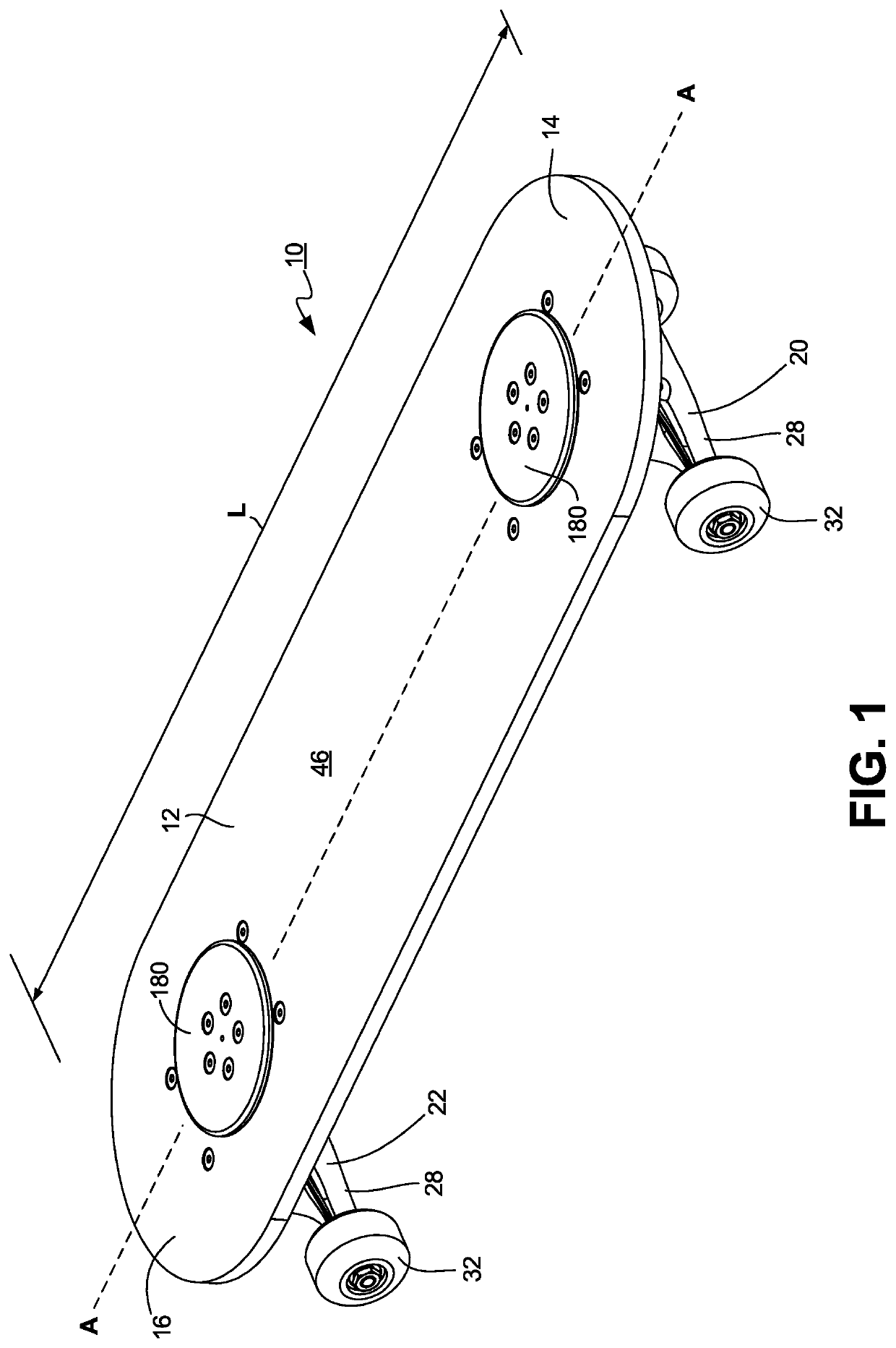
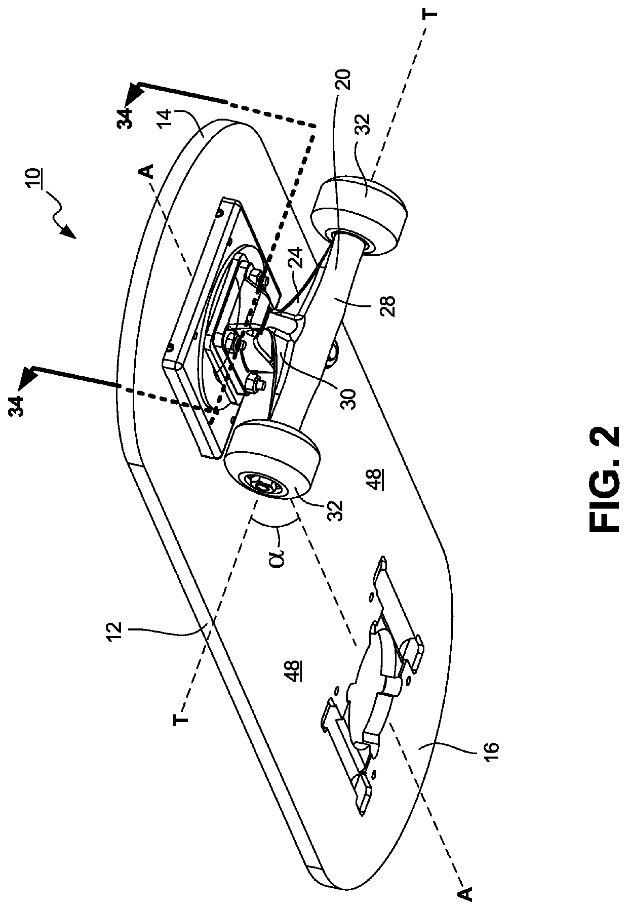
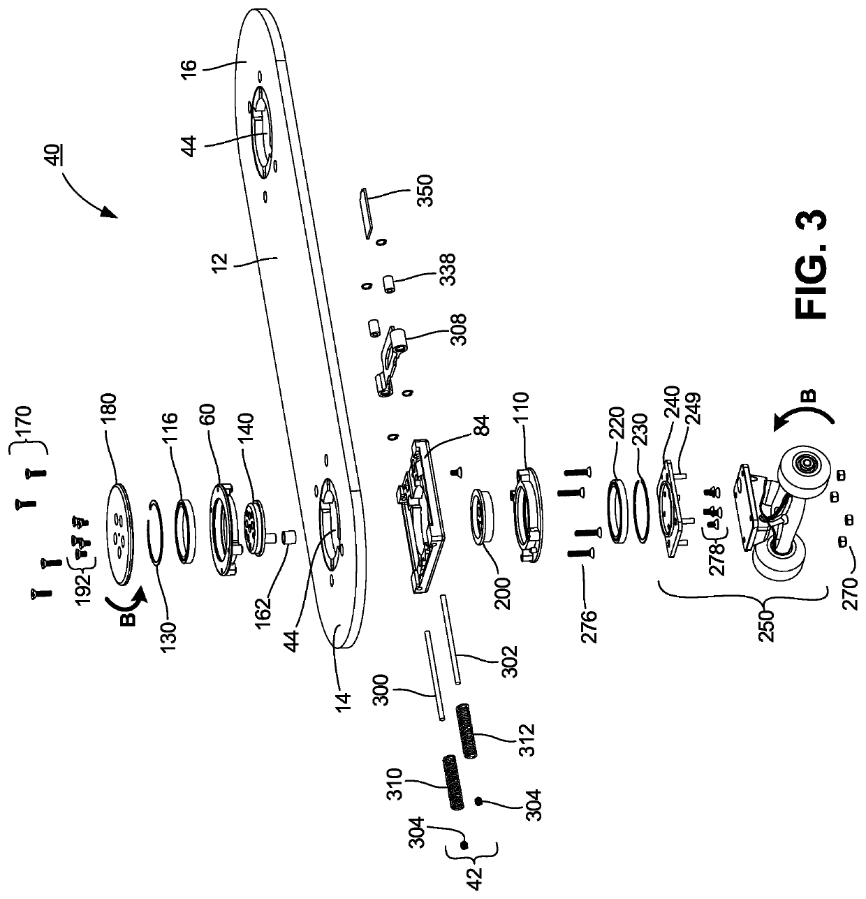
A roller board device like a skateboard or scooter operated by a user with one or more user-maneuverable wheel assemblies that are automatically returned to their “true north” position is provided according to the invention. The roller board device comprises an elongated deck, at least one wheel assembly, a rotation assembly operatively engaging and extending through the opening in the deck, one end of the rotation assembly being connected to the wheel assembly positioned below the deck, the other end of the rotation assembly being connected to a user interface member extending upward beyond the top surface of the deck, and a north-seeking return mechanism secured to the deck containing an engagement member movable along a linear axis within a housing and engaging a spring disposed between the engagement member and an interior wall of the housing, the rotation assembly operatively connected to the engagement member to convert rotational movement of the rotation member into linear movement of the engagement member. When the user applies rotational force to the user engagement member to turn it to the left or right, the rotation assembly and wheel assembly are rotated in the same direction and degree to allow the roller board device to be turned, the rotated rotation assembly interacting with the engagement member of the north-seeking return mechanism to move the engagement member along its linear axis to a retracted position to compress the spring. But, when the user releases the rotational force upon the user interface member, the spring extends from its compressed state to its elongated state to move the engagement member of the north-seeking return mechanism back along the linear axis from its retracted position to its standby position, counter interacting with the rotation assembly to return the wheel assembly of the roller board device to its true north position.

Description

CROSS-REFERENCE TO RELATED APPLICATION[0001]This application is a continuation-in-part of U.S. Ser. No. 15 / 897,943 filed on Feb. 15, 2018, which is a continuation-in-part of U.S. Ser. No. 15 / 433,842 filed on Feb. 15, 2017, both of which are hereby incorporated in their entirety.FIELD OF THE INVENTION[0002]The present invention relates to self-propelled roller boards like skateboards and scooters, and more particularly to a skateboard or scooter with one or more steerable trucks that may be independently maneuvered by the user while riding the skateboard or scooter to steer it in a desired direction, and automatically returned to their standby “true north” position once the user is no longer steering them.BACKGROUND OF THE INVENTION[0003]Skateboarding has become a popular recreation and sport. Derived from the late-1940's surfing scene in California as an activity for when the waves were flat, early skateboards were comparatively primitive devices comprising wooden boxes with roller ...

Claims


Application Information

Patent Timeline
Patent Type & Authority Patents(United States)
IPC IPC(8): A63C17/01B62K21/10B62K21/24B62K3/00
CPCB62K21/24B62K3/002B62K21/10
Inventor CLOS, DAVEVETTER, WILLIAM CHARLESPONGRATZ, TROY A.
Owner ROLL INC
Learn More