
Aluminum chip dryers

a dryer and aluminum chip technology, applied in drying machines, lighting and heating apparatus, furnaces, etc., can solve the problems of high cost and unsuitability, dangerous situation of moisture expansion or explosion in the furnace, and the contaminated oil of machined chips, etc., and achieve the effect of higher emissivity

Inactive Publication Date: 2014-02-13
PYROTECK INC
View PDF7 Cites 78 Cited by
  • Summary
  • Abstract
  • Description
  • Claims
  • Application Information

AI Technical Summary

Benefits of technology

This patent describes a dryer that removes hydrocarbons and moisture from metal chips. The dryer has a chamber with a top portion and a base portion, and a burner that introduces heated gas into the top portion. There is also a device that transfers metal chips from an inlet to an outlet. The second embodiment describes a dryer with a conveyor that extends between the inlet end and the outlet end. These two configurations provide different methods to effectively dry metal chips using a dryer.

Problems solved by technology

The machined chips will therefore be contaminated with oil.
However, this is an expensive method and not desirable from an environmental point of view.
However, the high moisture and hydrocarbon content in the material creates a dangerous situation of moisture expansion or explosion within the furnace.
In addition, the hydrocarbon content will create contamination, melt loss and excessive smoking.
Accordingly, direct introduction of the material into a molten metal environment is, for all practical purposes, nearly impossible.

Method used


Image

  • Aluminum chip dryers
  • Aluminum chip dryers
  • Aluminum chip dryers

Examples


Embodiment Construction

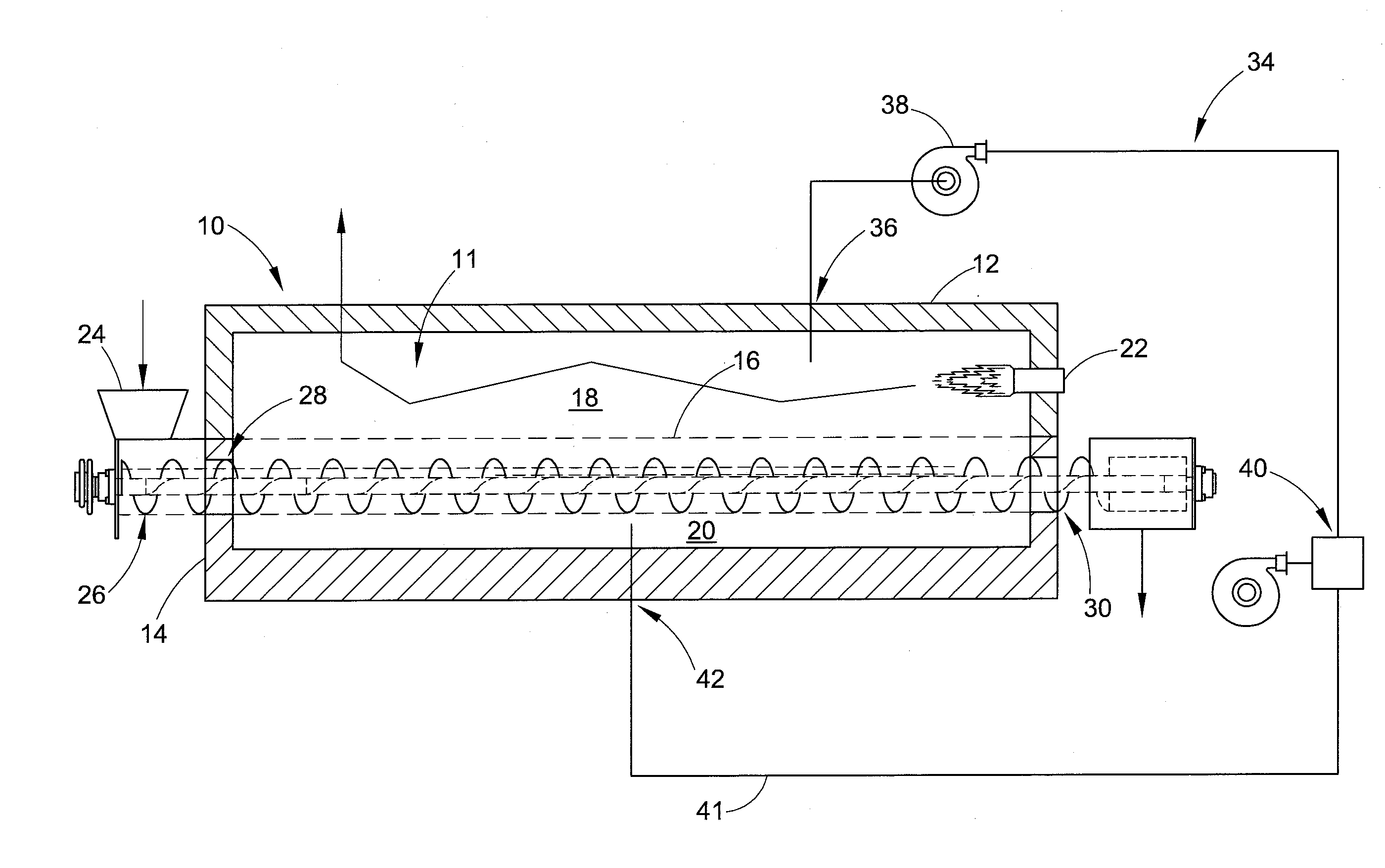
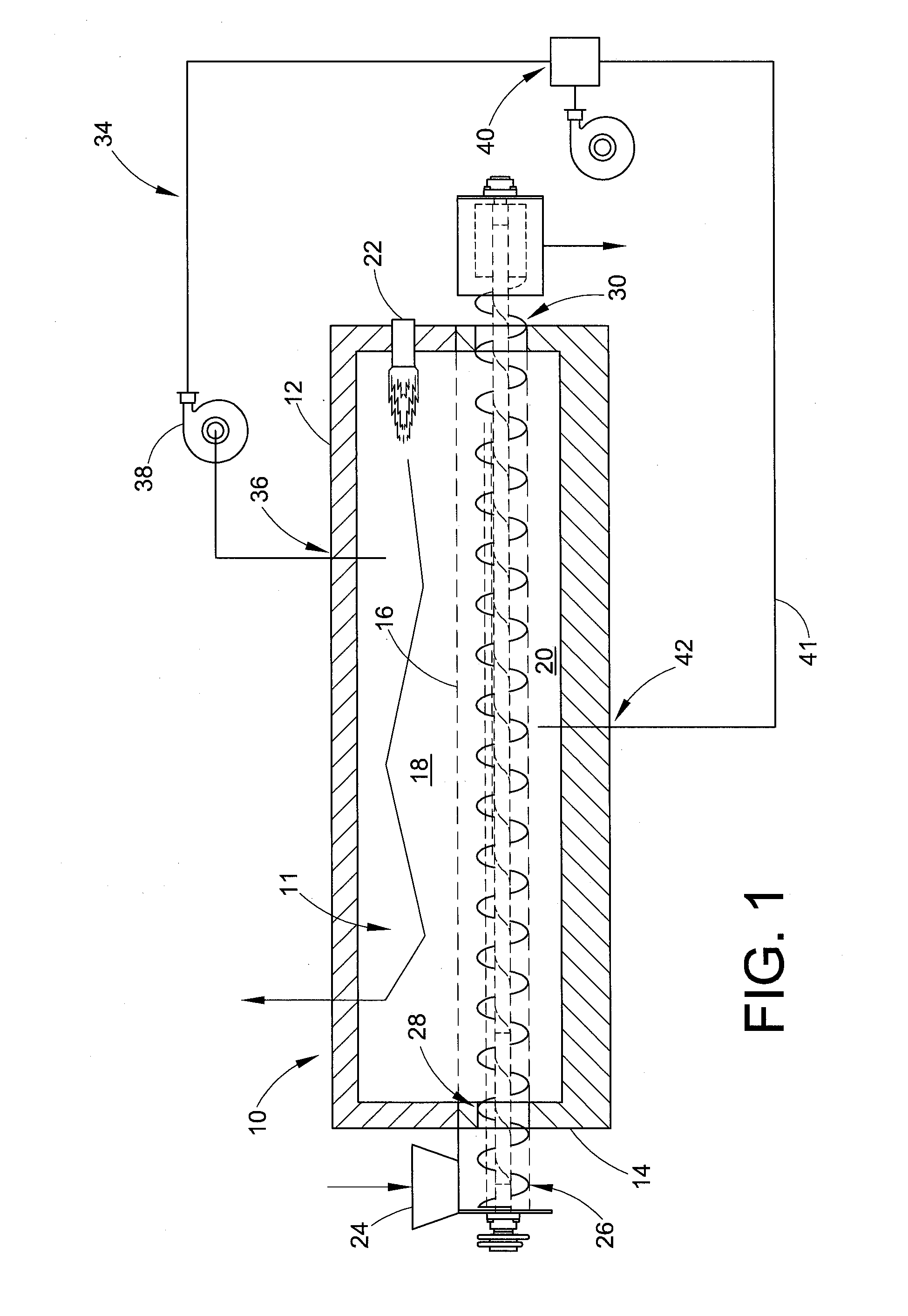
[0010]According to a representative embodiment, a two zone drying system is provided. Zone 1 is the main burner heated chamber where thermal oxidation of the VOC from the chips takes place. Zone 1 is a hotter radiant zone (about 1400° F.) with walls formed of a high emissivity material which radiates heat down to the chips on a screw conveyor in Zone 2 to aid in drying. The 1400° F. in Zone 1 thermally oxidizes the VOC exhaust from the drying process in Zone 2. Zone 2 is a somewhat cooler zone and uses a lower emissivity material. Zone 2 also receives recirculated air cooled to 1000° F. or lower from Zone 1. This air is cooled by an in-line heat exchanger 40 (HX) so the oxygen levels are kept low (no fresh air quenching) but fresh air quenching can be used as appropriate. The recirculation air also insures that the chips in Zone 2 do not get above 1000 F (where melting and oxidation occur).

[0011]With reference to FIG. 1, a furnace 10 is provided which includes a top portion 12 const...


PUM


Abstract

In accordance with one aspect of an exemplary embodiment, a dryer for removing hydrocarbons and / or moisture from metal chips is provided. The dryer has a chamber including a top portion and a base portion. The top portion is comprised of a material having a higher emissivity than the material forming the base portion. A burner is provided which introduces heated gas into the top portion. A device for transporting the metal chips is provided in the base portion. The device receives the metal chips at an inlet and transporting the metal chips to an outlet.

Description

BACKGROUND[0001]This disclosure relates to a method for the treatment of waste products, in particular, waste products of metals which are contaminated with water, oil and oleaginous cooling agents, and to an apparatus for carrying out such method.[0002]When metals are machined, a number of waste products are automatically produced in the form of particles or chips, e.g. fillings, turnings, borings or machining chips. In the machining of metals, for example, aluminum and aluminum alloys, oil or oil containing cooling fluids may be employed. The machined chips will therefore be contaminated with oil. In a typical situation, the borings and turnings will include, by weight, from 2 to 20 percent of the cutting oil. The use of solvents will remove the oil from the oil-coated chips quite well. However, this is an expensive method and not desirable from an environmental point of view.[0003]Nonetheless, recovery of the scrap borings, turnings and chips is desirable in view of the cost of b...

Claims


Application Information

Patent Timeline
Patent Type & Authority Applications(United States)
IPC IPC(8): F26B21/02
CPCF26B21/02F26B21/04F26B23/02F26B23/002
Inventor VILD, CHRISBENDLAK, ROBERTGRAYSON, JAMESBOLTON, MARKREYNOLDS, MARKQUILTER, DAVID
Owner PYROTECK INC
Learn More