Stent-Valves For Valve Replacement and Associated Methods and Systems for Surgery

a valve replacement and valve valve technology, applied in the field of valve replacement valve valve valve valve valve and associated methods and surgical procedures, can solve the problems of increasing the risks, death, and limiting patients' activities, and achieve the effect of facilitating a surgical approach and reducing risks

Active Publication Date: 2014-02-06
BOSTON SCI LTD
View PDF14 Cites 42 Cited by
  • Summary
  • Abstract
  • Description
  • Claims
  • Application Information

AI Technical Summary

Benefits of technology

The present invention is about systems, methods, and devices for cardiac valve replacement. The invention offers a minimally-invasive surgical approach for replacing failed valves in the heart without the need for an open-chest cavity and heart-lung bypass. The invention includes stent-valves, a delivery system, and an apparatus for positioning and attaching a stent-valve. The technical effects of the invention include reducing the risks associated with replacing a failed native valve in the first instance, as well as the risks associated with secondary or subsequent surgeries to replace failed artificial valves. The stent-valve delivery system includes a coil-reinforced outer sheath and a stoat holder with proximal and distal components. The stent holder includes at least one chamfered edge adjacent to attachment pins for easy release and expansion of the stent-valve from the stent holder. The apparatus includes an elongate, pliable member and a tube for engagement of attachment elements to attachment pins. The invention offers a safer and more effective therapy for cardiac-valve replacement.

Problems solved by technology

However, tissue adherences resulting from the first surgery may increase the risks (e.g., death) associated with subsequent valve replacement surgeries.
Such anti-coagulant treatment significantly limits patients' activities and can cause various other complications.
Biological valves do not require such anti-coagulation treatment but typically fail within 10-15 years.
These PHVT attempts have various shortcomings, including their inability to ensure proper positioning and stability of the replacement valve within the patient's body.

Method used


Image

  • Stent-Valves For Valve Replacement and Associated Methods and Systems for Surgery
  • Stent-Valves For Valve Replacement and Associated Methods and Systems for Surgery
  • Stent-Valves For Valve Replacement and Associated Methods and Systems for Surgery

Examples


Embodiment Construction

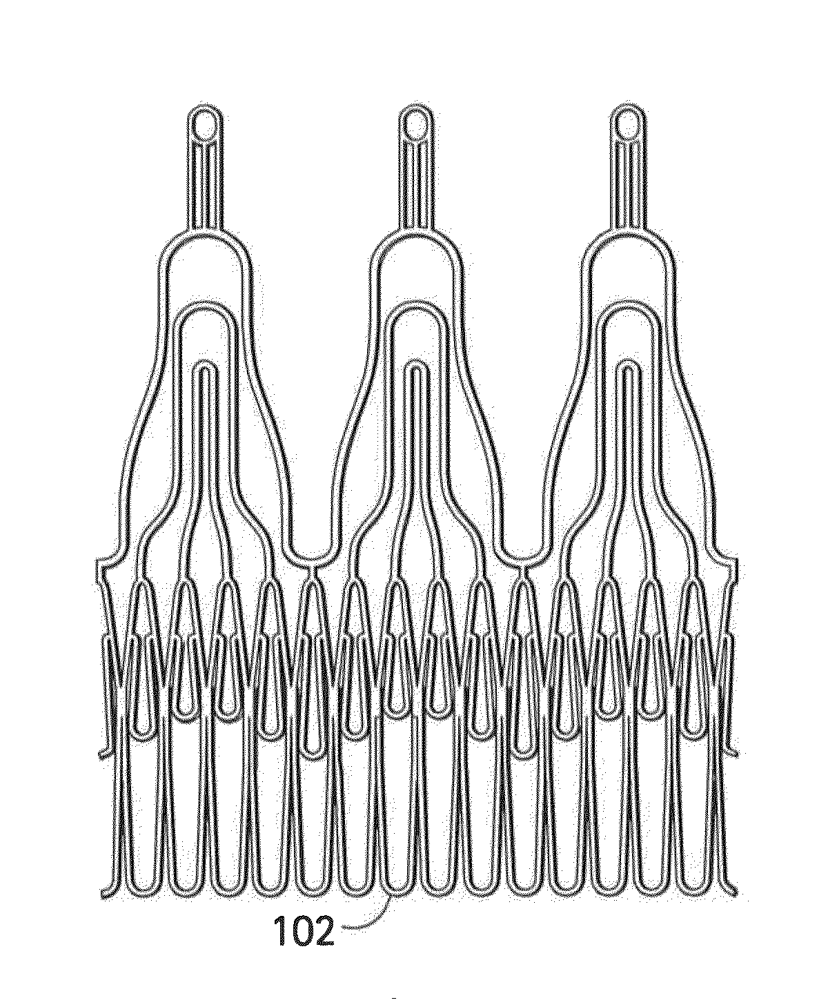
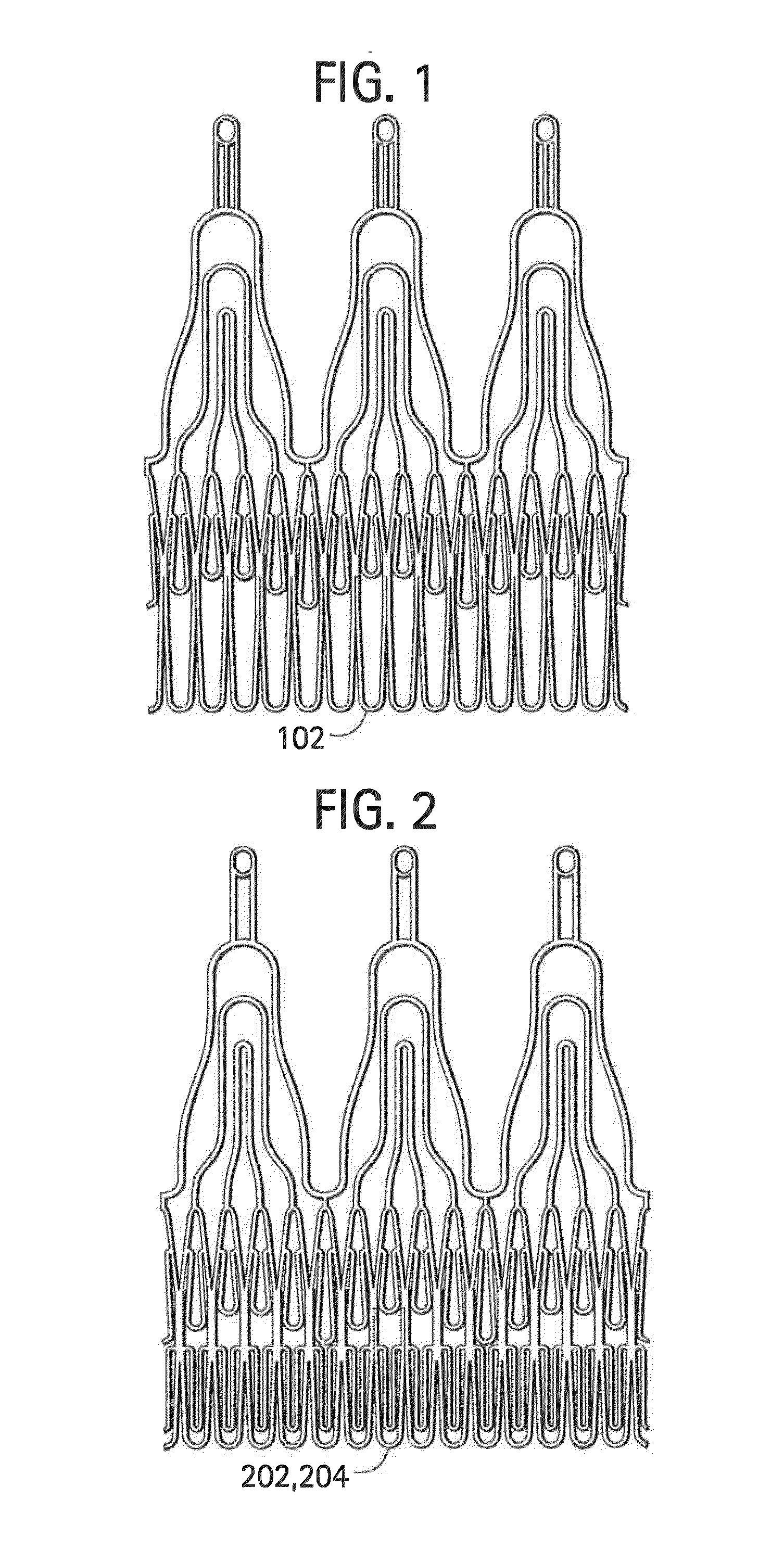
[0037]FIG. 1 shows a stent component according to some embodiments that includes single struts 102 in a proximal section of the stent. FIG. 2 shows a stent component according to some embodiments that includes two struts (202, 204) in a proximal section of the stent. Such double struts may increase the radial resistance to crush of the stent (e.g., axial resistance) and the out of plane bending stiffness of the stent proximal section, thus improving the anchoring of the stent within, for example, a failed biological valve or a calcified native annulus. In FIG. 1, multiple (e.g., 10-15 or more) installations of single strut 102 may be provided, for example, side-by-side around the circumference of the scent. In FIG. 2, first strut 202 and second strut 204 are provided, where second strut 204 may be a reinforcement within first strut 202.

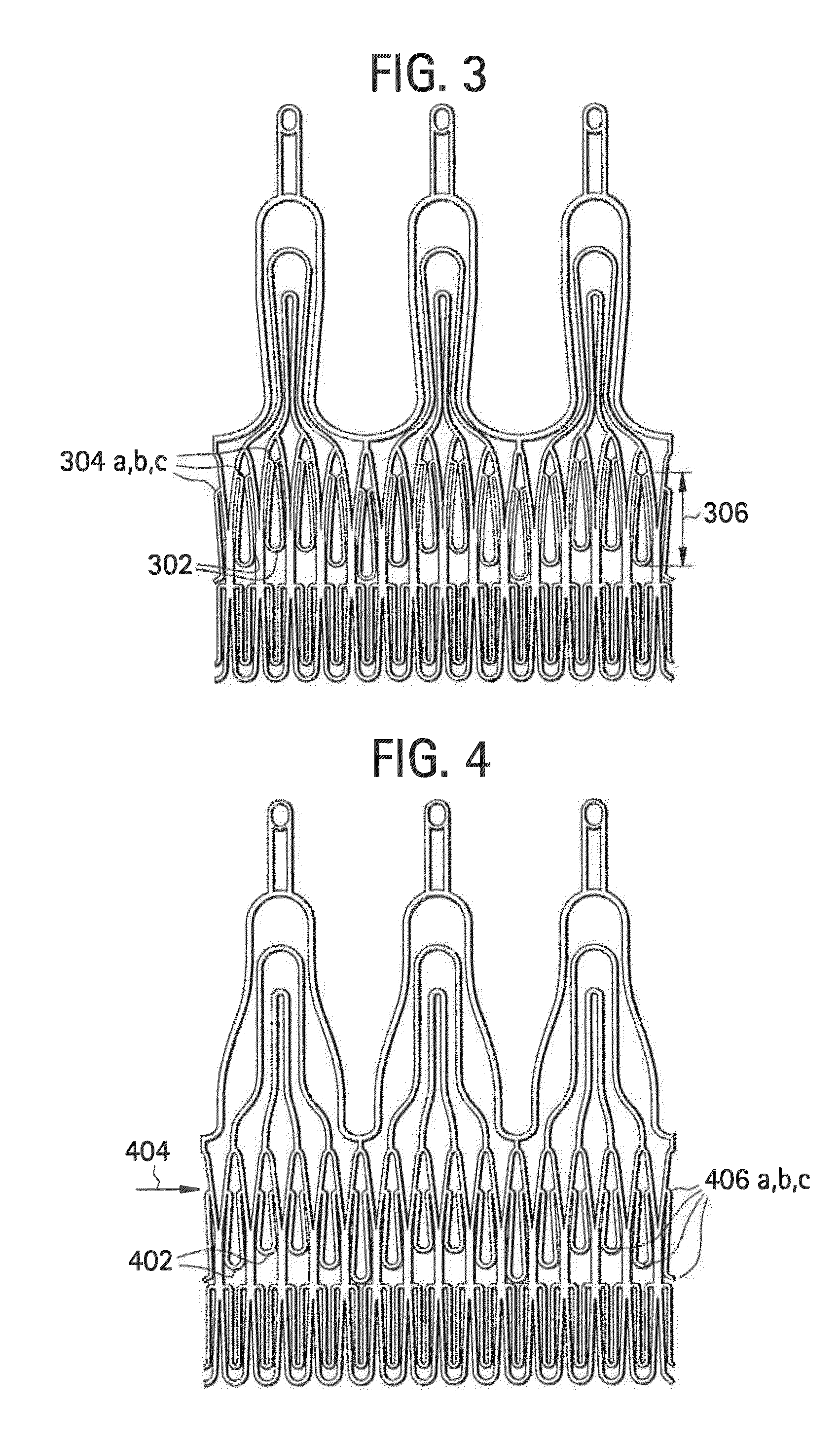
[0038]FIGS. 3 and 4 show some embodiments of stent components that include multiple locking elements positioned at multiple, different levels, such t...


PUM


Abstract

Stent-valves (e.g., single-stent-valves and double-stent-valves) and associated methods and systems for their delivery via minimally-invasive surgery are provided.

Description

BACKGROUND OF THE INVENTION[0001]Conventional approaches for cardiac valve replacement require the cutting of a relatively large opening in the patient's sternum (“sternotomy”) or thoracic cavity (“thoracotomy”) in order to allow the surgeon to access the patient's heart. Additionally, these approaches require arrest of the patient's heart and a cardiopulmonary bypass (i.e., use of a heart-lung bypass machine to oxygenate and circulate the patient's blood). Despite their invasiveness, these surgical approaches may be reasonably safe for a first intervention. However, tissue adherences resulting from the first surgery may increase the risks (e.g., death) associated with subsequent valve replacement surgeries. See Akins et al., “Risk of Reoperative Valve Replacement for Failed Mitral and Aortic Bioprostheses”, Ann Thorac Surg 1998; 65:1545-52; and Weerasinghe et al., “First Redo Heart Valve Replacement—A 10-Year Analysis”, Circulation 1999; 99:655-658; each of which is incorporated by...

Claims


Application Information

Patent Timeline
IPC IPC(8): A61F2/24
CPCA61F2/2418A61F2/243A61F2/2436A61F2250/0018A61F2220/0075
Inventor DELALOYE, STEPHANEHEFTI, JEAN-LUCDELALOYE, SERGE
Owner BOSTON SCI LTD
Why Eureka
Try Eureka