
Optical sheet guide member, and backlight unit having the optical sheet guide member

a technology of optical sheet guide and optical sheet guide, which is applied in the field of backlight units, can solve the problems of increasing manufacturing time, increasing costs, and reducing such areas or widths

Inactive Publication Date: 2014-02-06
SAMSUNG DISPLAY CO LTD
View PDF9 Cites 5 Cited by
  • Summary
  • Abstract
  • Description
  • Claims
  • Application Information

AI Technical Summary

Benefits of technology

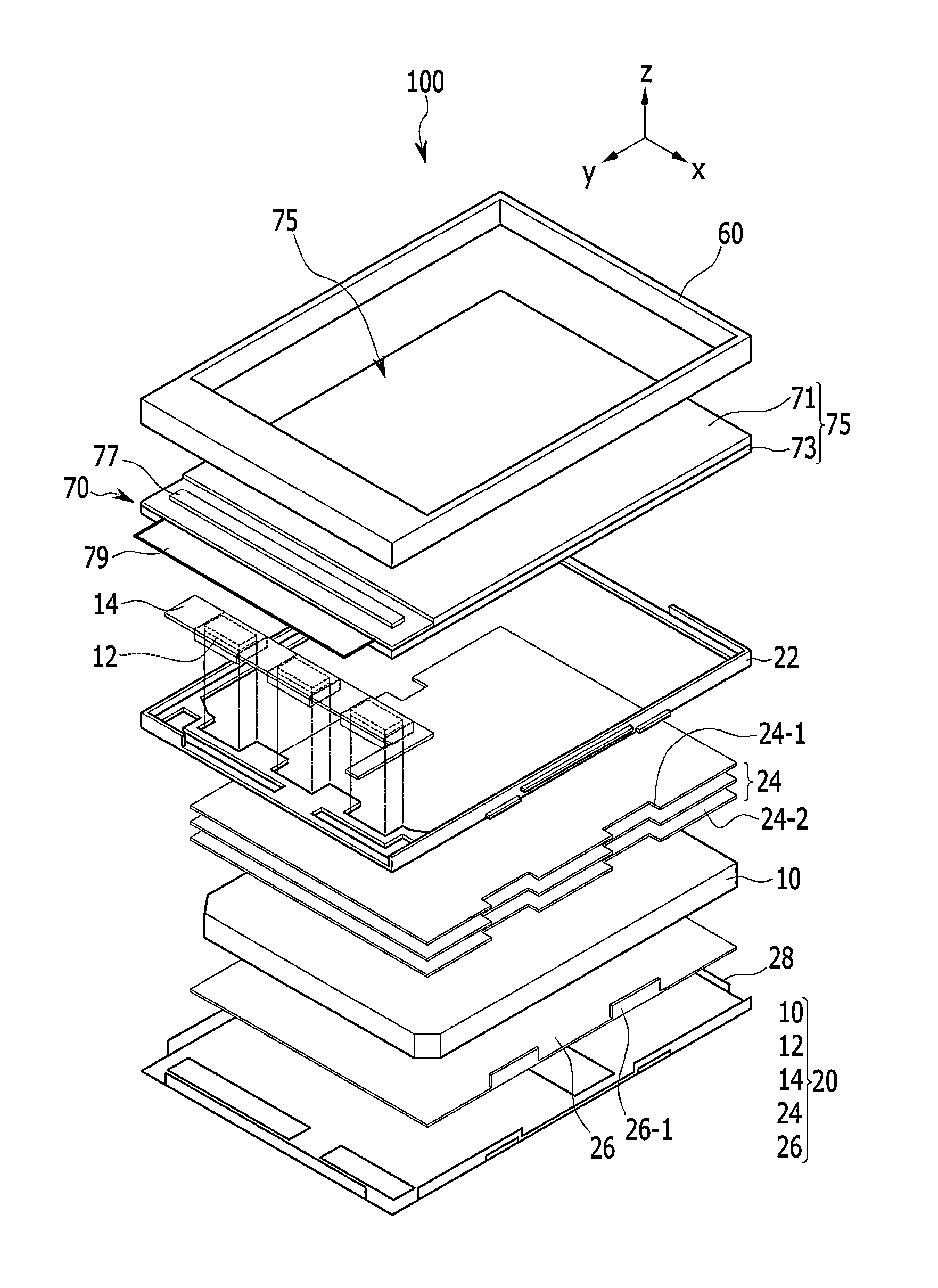
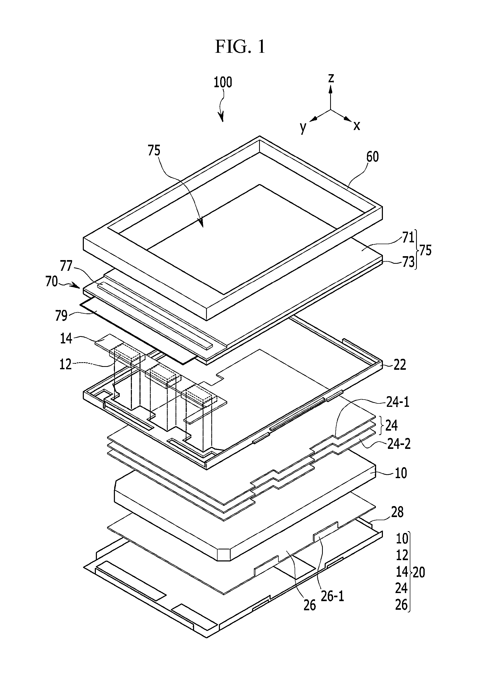
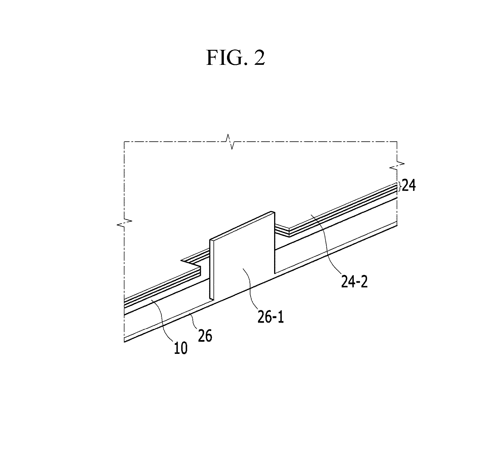
The invention provides a backlight unit that can easily fix an optical sheet with low cost and processing time. The backlight unit includes a light source, a light guide, an optical sheet, and a reflection sheet. The optical sheet is fixed on the light guide through a protrusion guide member on the reflection sheet and a corresponding guide member on the optical sheet. This allows for a narrower bezel of a liquid crystal display and / or the backlight unit.

Problems solved by technology

However, since the additional fixing member at the chassis is accommodated in an area or width of the liquid crystal display and / or the backlight unit surrounding the optical sheet, reducing such area or width may be undesirably limited.
Also, to form the additional fixing member at the chassis, a shape of the additional fixing member must be added to a mold of the chassis such that there are drawbacks since a manufacturing process is complicated, a manufacturing time is increased and a cost is increased.

Method used


Image

  • Optical sheet guide member, and backlight unit having the optical sheet guide member
  • Optical sheet guide member, and backlight unit having the optical sheet guide member
  • Optical sheet guide member, and backlight unit having the optical sheet guide member

Examples


Embodiment Construction

[0044]The invention will be described more fully hereinafter with reference to the accompanying drawings, in which exemplary embodiments of the invention are shown. As those skilled in the art would realize, the described embodiments may be modified in various different ways, all without departing from the spirit or scope of the invention.

[0045]In the drawings, the thickness of layers, films, panels, regions, etc., are exaggerated for clarity. Like reference numerals designate like elements throughout the specification. As used herein, connected may refer to elements being physically and / or electrically connected to each other. Like numbers refer to like elements throughout. As used herein, the term “and / or” includes any and all combinations of one or more of the associated listed items.

[0046]It will be understood that when an element such as a layer, film, region, or substrate is referred to as being “on” another element, it can be directly on the other element or intervening eleme...


PUM


Abstract

A backlight unit includes a light source which supplies light; a light guide which transmits the light; an optical sheet on the light guide, and including a guide member extending from a side surface of the optical sheet; and a reflection sheet under the light guide. The reflection sheet reflects the light toward the optical sheet and includes a protrusion guide member which extends from a side surface of the reflection sheet and toward the light guide. The guide member of the optical sheet is coupled to the protrusion guide member of the reflection sheet, and restricts movement of the optical sheet.

Description

[0001]This application claims priority to Korean Patent Application No. 10-2012-0084954 filed on Aug. 2, 2012, and all the benefits accruing therefrom under 35 U.S.C. §119, the entire contents of which are incorporated herein by reference.BACKGROUND[0002](a) Field[0003]The invention relates to a backlight unit.[0004](b) Description of the Related Art[0005]Based on semiconductor technology which has been rapidly developed, demand for a flat panel display having more improved performance due to a small size and a light weight has explosively increased.[0006]A liquid crystal display (“LCD”) which has been in the spotlight among the flat panel displays has merits of a small size, a light weight, low power consumption, and the like. Accordingly, the liquid crystal display has gradually gained more attention as an alternative display capable of overcoming demerits of a known cathode ray tube (“CRT”) and is used in a number of information processing devices where display devices are requir...

Claims


Application Information

Patent Timeline
Patent Type & Authority Applications(United States)
IPC IPC(8): F21V8/00
CPCG02B6/0055G02B6/0088G02F1/1333G02F1/1335
Inventor JEONG, WEE-JOON
Owner SAMSUNG DISPLAY CO LTD
Learn More