
Source for electromagnetic surveying

Inactive Publication Date: 2014-02-06
ELECTROMAGNETIC GEOSERVICES ASA
View PDF5 Cites 7 Cited by
  • Summary
  • Abstract
  • Description
  • Claims
  • Application Information

AI Technical Summary

Benefits of technology

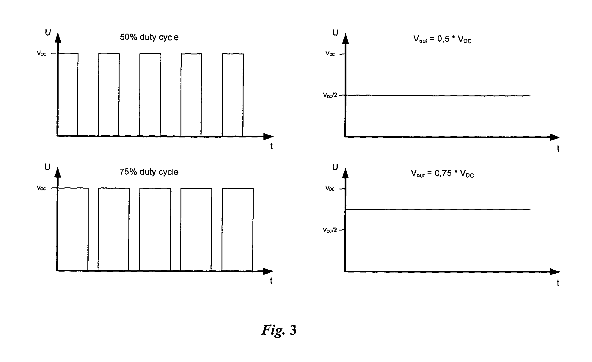
The present invention provides a system and method for generating an EM signal with more accuracy and flexibility in frequency range for use in different surveys. This allows for better tailoring of an EM source signal for a specific subterranean prospect and increased signal to noise ratios, resulting in increased accuracy of EM data. The system and method of embodiments of the invention can be beneficial for investigating targets at large depths beneath the seabed and improves surveys in areas with complex geology and small targets. The invention achieves this by producing a high-current wideband EM signal with sharp transition characteristics, using a HED antenna. Data obtained using this signal is of increased accuracy, and the transmitted EM signal is largely independent of the AC power input characteristics. This increases the accuracy of the generated EM field and the accuracy of survey data.

Problems solved by technology

However, whereas a seismic survey can reveal the location and shape of a potential reservoir, it cannot normally reveal the nature of the reservoir, for example, whether the reservoir contains hydrocarbons or water.
At present, electromagnetic surveying techniques are not widely used in practice.
Unfortunately, such short wavelengths suffer from very high attenuation.
Long wavelengths do not provide adequate resolution.
However, while longer wavelengths applied by electromagnetic techniques cannot provide sufficient information to provide an accurate indication of the boundaries of the various strata, if the geological structure is already known they can be used to determine the nature of a particular identified formation, if the possibilities for the nature of that formation have significantly differing electromagnetic characteristics.

Method used


Image

  • Source for electromagnetic surveying
  • Source for electromagnetic surveying
  • Source for electromagnetic surveying

Examples


Embodiment Construction

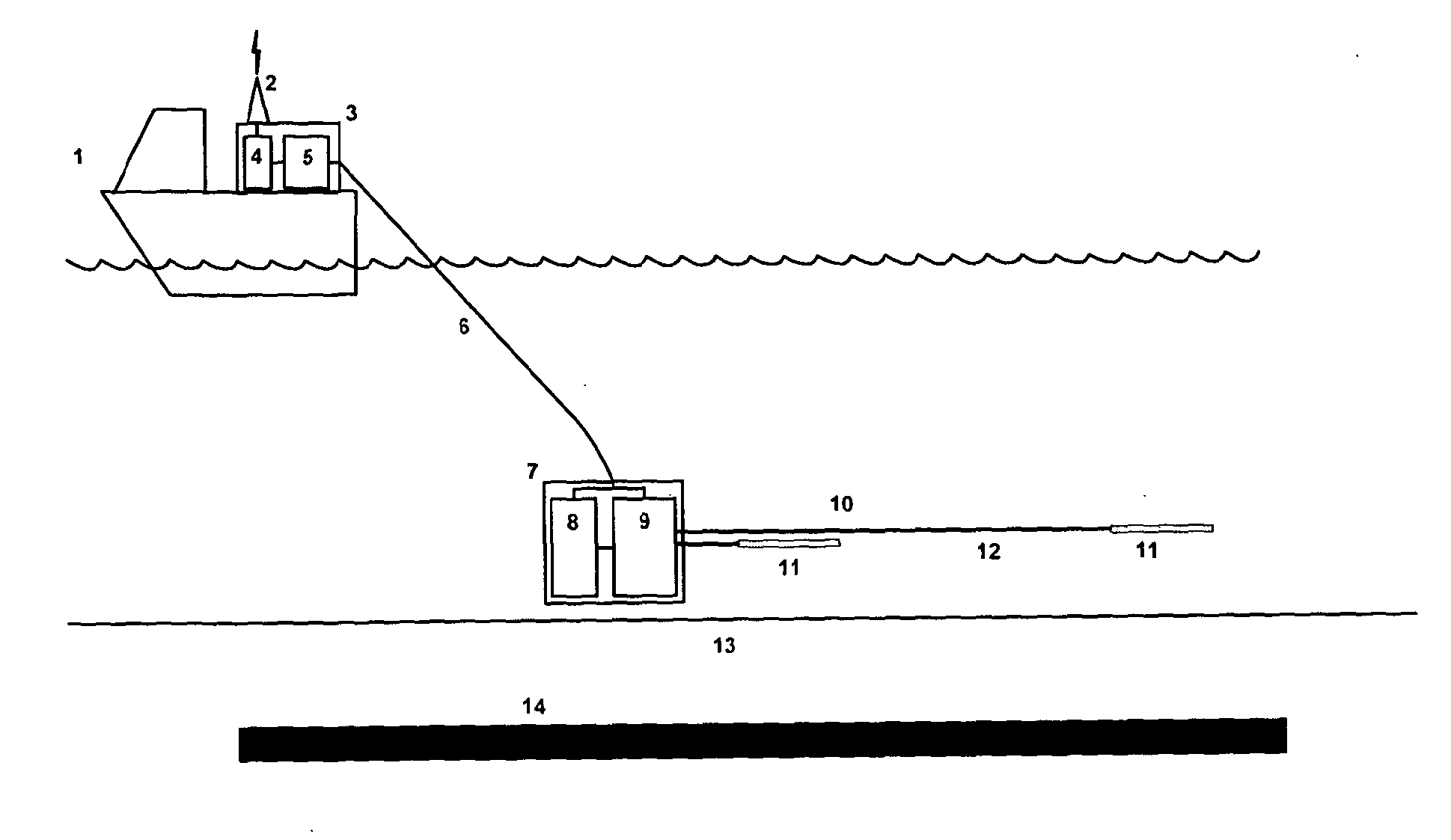
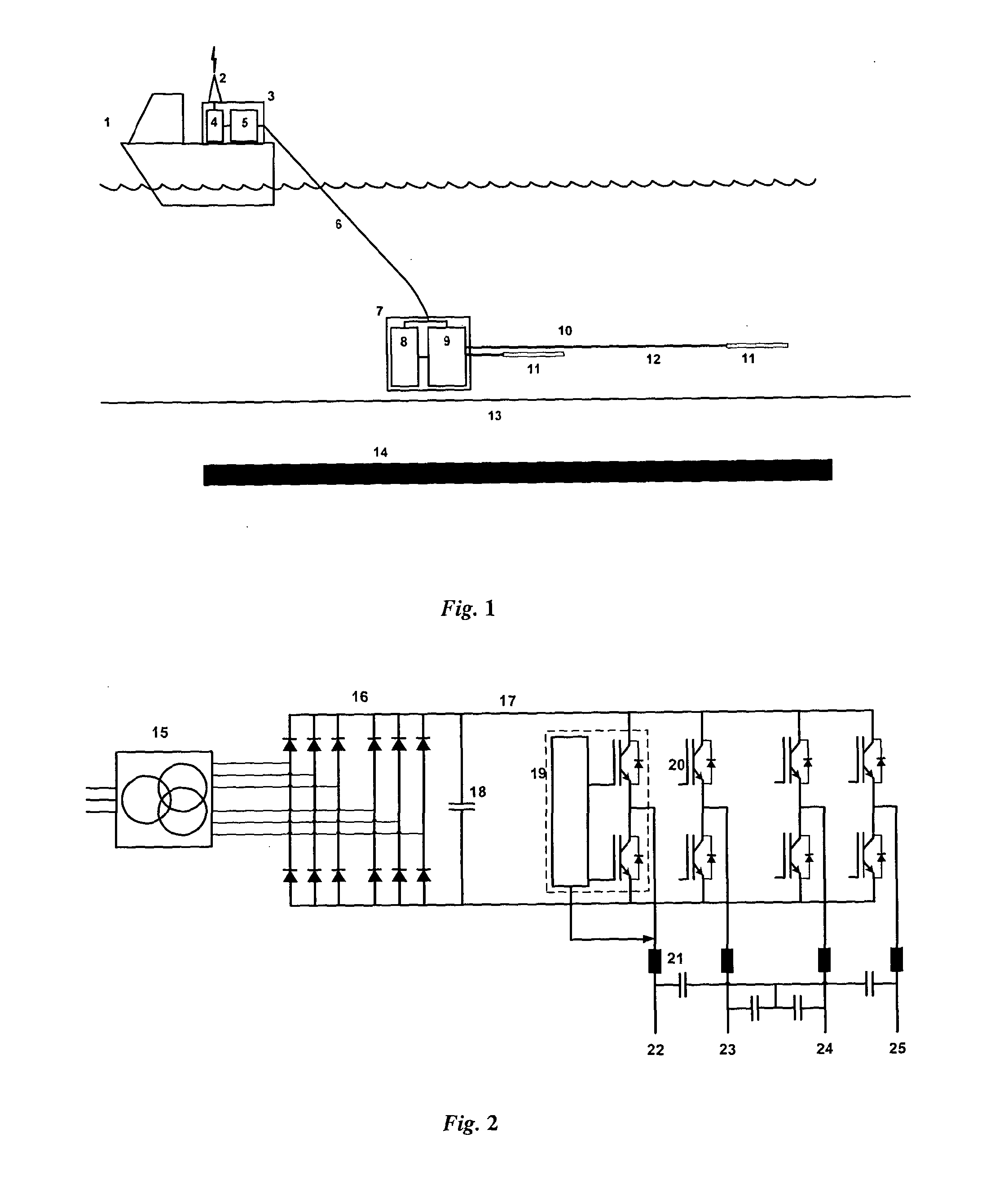
[0026]The topside PSU required by the system according to embodiments of the invention is typically located on a survey vessel. An example of this arrangement is shown in FIG. 1, where the survey vessel 1 carries the topside PSU 5. Alternatively, the topside PSU could be supported on land or located on a moving or stationary support. If the survey is being carried out in relatively shallow water, for example in water depths of 500 m or less, the PWM current source may be located out of the water, near the topside PSU, for example on the same survey vessel. If the survey is being carried out in deeper water, the PWM current source may be submersible, so that it can be operated at depths near the HED. In that case, the PWM current source will be connected to the topside PSU via an umbilical, which may comprise 3-phase high voltage main power conductors, auxiliary power conductors and a fibre optic communication link. The umbilical may be armored and serve as a tow cable for the PWM cu...


PUM


Abstract

A submersible high current PWM-based source system for marine electromagnetic surveying for hydrocarbon exploration. The system converts a periodic, arbitrary digital signal to a high output current in a HED optimized for maximum dipole moment, using PWM modulation and real-time current regulation for precise output amplitude. The design and choice of components allows a wideband EM signal to be generated with sharp transition characteristics and substantially independent of the AC input power characteristics. This in turn enables for improved tailoring of an EM source signal for a specific subterranean prospect, and thus increased accuracy of the EM data.

Description

RELATED APPLICATIONS[0001]The present application is a National Phase entry of PCT Application No. PCT / GB2012 / 000088, filed Jan. 27, 2012, which claims priority from GB Application No. 1101576.5, filed Jan. 28, 2011, which applications are hereby incorporated by reference herein in their entirety.TECHNICAL FIELD[0002]The present invention relates to a source for electromagnetic (EM) surveying, in particular for seabed logging, and a method for producing a signal for EM surveying.BACKGROUND ART[0003]Currently, the most widely used techniques for geological surveying, particularly in sub-marine situations, are seismic methods. These seismic techniques are capable of revealing the structure of the subterranean strata with some accuracy. However, whereas a seismic survey can reveal the location and shape of a potential reservoir, it cannot normally reveal the nature of the reservoir, for example, whether the reservoir contains hydrocarbons or water.[0004]However, while the seismic prope...

Claims


Application Information

Patent Timeline
IPC IPC(8): G01V3/20
CPCG01V3/20G01V3/12G01V3/17
Inventor RAMSFJELL, HAVARDJENSEN, HANS ROGERELLINGSRUD, SVEIN
Owner ELECTROMAGNETIC GEOSERVICES ASA
Learn More