
Method for sensor reader calibration

a sensor reader and calibration method technology, applied in the field of chemical and biological sensors, can solve the problems of difficult to accurately sense and discern a specific type of vapor or vapor mixture being sensed, limited array capability for sensing only a single response, and complicating array fabrication, so as to achieve the effect of reducing environmental parameters

Active Publication Date: 2014-01-30
GENERAL ELECTRIC CO
View PDF23 Cites 37 Cited by
  • Summary
  • Abstract
  • Description
  • Claims
  • Application Information

AI Technical Summary

Benefits of technology

This patent describes a method for calibrating sensors by measuring the impedance of the sensor at different power levels and then using those measurements to correct for environmental factors. The result is that the sensor's response is more accurate, regardless of the external conditions it may be exposed to.

Problems solved by technology

However, while using identical sensors simplifies fabrication of the sensor array, such an array may have limited capabilities for sensing only a single response (e.g. resistance, current, capacitance, work function, mass, optical thickness, light intensity, etc).
Disadvantageously, fabricating a sensor array having individual sensors uniquely fabricated to sense a particular response complicates fabrication of the array.
The greater the number of vapors and vapor mixtures that may be present, the more difficult it may be to accurately sense and discern a specific type of vapor or vapor mixture being sensed.
For instance, high humidity environments often interfere with the ability of traditional sensors to detect selected vapors.
Moreover, variability and inconsistencies exist due to the sensor, environmental parameters, and within the sensor reader itself.
A sensor reader is susceptible to environmental parameters, such as temperature.

Method used


Image

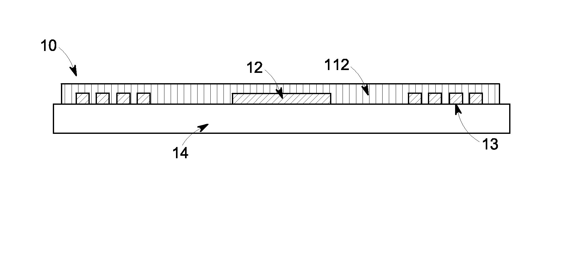
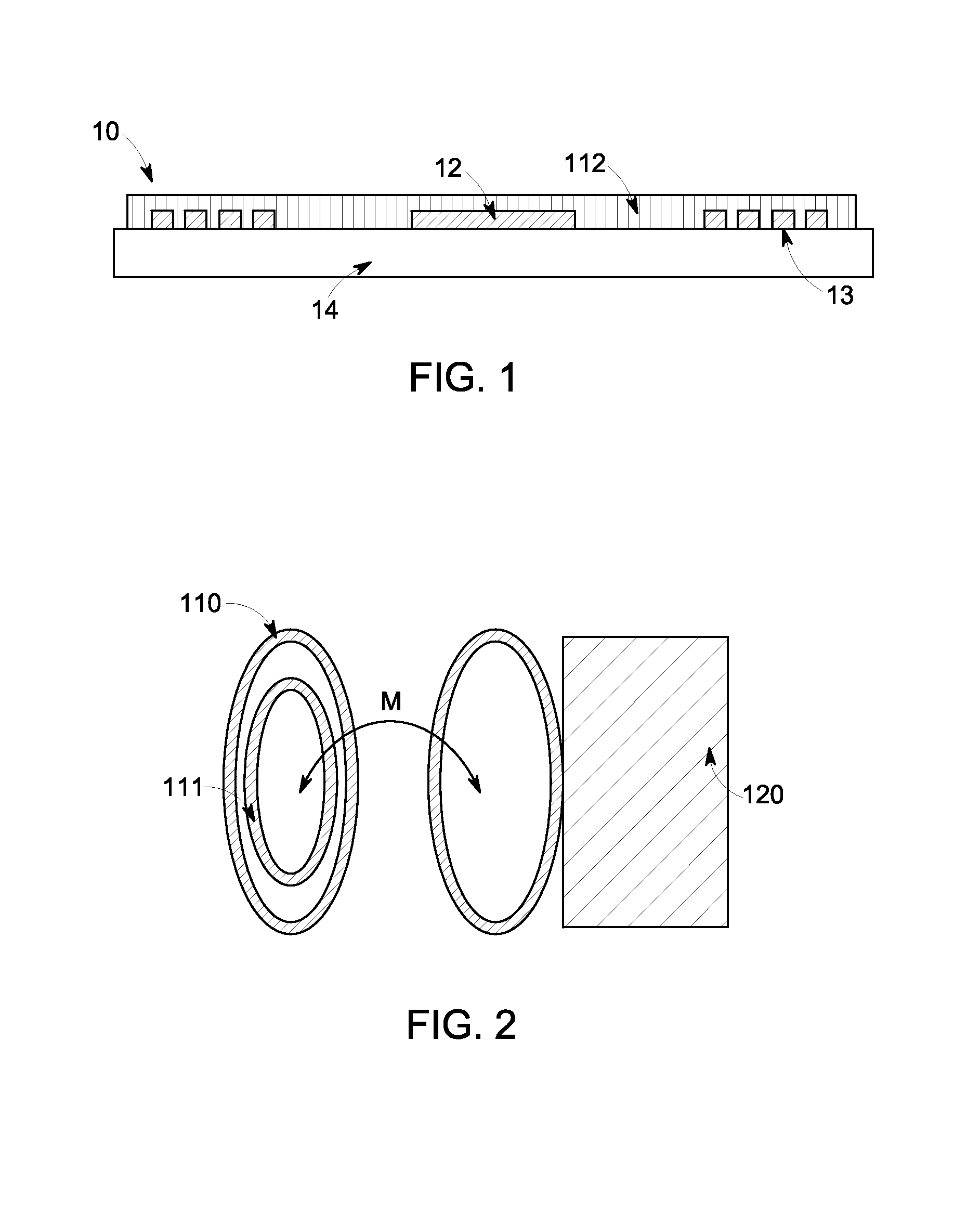
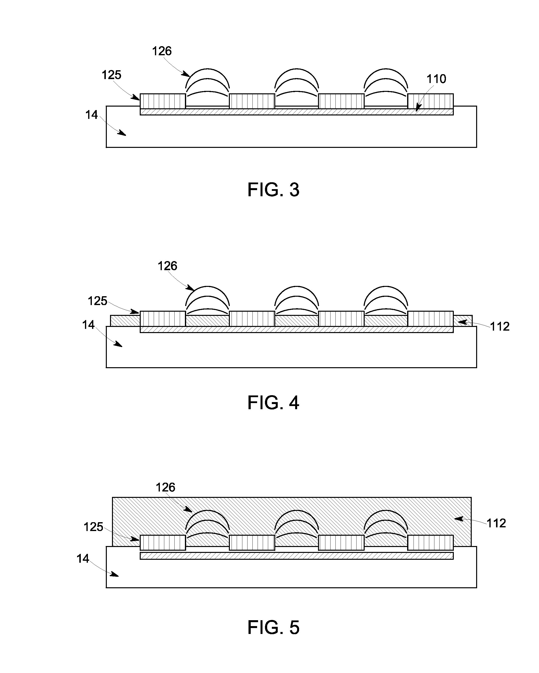
  • Method for sensor reader calibration
  • Method for sensor reader calibration
  • Method for sensor reader calibration

Examples


Embodiment Construction

[0026]Embodiments enclosed herein provide methods for the sensitivity, selectivity, and stability of sensors wherein a sensor is provided and is capable of detecting multiple environmental changes and translating these changes into a resonance enhanced impedance measurement. Non-limiting examples of such multiple environmental changes include individual vapors in their multi-vapor mixtures of a gaseous sample such as air, temperature of the sample and sensor, pressure of ambient air. To accomplish this measurement of multiple environmental changes, a resonant transducer is built and is put in contact with a sensing material.

[0027]To more clearly and concisely describe the subject matter of the claims invention the following definitions are provided for specific terms, which are used in the following description and the appended claims.

[0028]The term “sensor” and / or “sensing coil” is used to describe a resonant transducer substantially in contact with a sensing material or sensor fil...


PUM


Abstract

In one embodiment a method for sensor reader calibration comprising: performing a calibration of a sensor reader wherein the calibration comprises open circuit calibration, a short circuit calibration, and a load circuit calibration, or any combination thereof in any succession; enabling connection of a pickup coil to the sensor reader to measure a sensor response; and applying a baseline correction to the sensor response, wherein the baseline correction is obtained utilizing measurements from the calibration step. In a further embodiment, a method for sensor response calibration incorporating environmental correction comprising: measuring a first resonance impedance spectrum of the sensor with a first applied power to the pickup coil; measuring a second resonance impedance spectrum of the sensor with a second applied power to the pickup coil; and applying a correction to the sensor response corresponding to the respective measured first and second resonance impedance spectrum to mitigate for environmental parameters.

Description

CROSS REFERENCE TO RELATED APPLICATION[0001]The present application is a continuation in part (CIP) of U.S. patent application Ser. No. 13 / 558,499 filed on Jul. 26, 2012.BACKGROUND[0002]The subject matter disclosed herein relates to chemical and biological sensors, and more particularly, the recalibration of a sensor reader to mitigate for environmental parameters.[0003]Chemical and biological sensors are often employed in a number of applications where the detection of various sensor signals may be used to discern useful information. For instance, measuring the presence of vapors by discerning a change in certain environmental variables within or surrounding a sensor may be particularly useful in monitoring changes in biopharmaceutical products, food or beverages, monitoring industrial areas for chemical or physical hazards, as well as in security applications such as residential home monitoring, homeland security in airports, in different environmental and clinical settings and ot...

Claims


Application Information

Patent Timeline
IPC IPC(8): G01R35/00
CPCG01R35/005G01N27/026G01N33/0006G01N33/0073G01N22/00G01N27/023G01N22/04A61B2560/0219A61B5/0031
Inventor POTYRAILO, RADISLAV ALEXANDROVICHFORSTER, IAN JAMES
Owner GENERAL ELECTRIC CO
Learn More