
Cell voltage monitoring and self-calibrating device

a self-calibrating and cell voltage technology, applied in measurement devices, instruments, computing, etc., can solve the problems of external components and integrated circuits, increased cost, and high cost of analog to digital converter calibration

Active Publication Date: 2014-01-23
HYCON TECH
View PDF14 Cites 3 Cited by
  • Summary
  • Abstract
  • Description
  • Claims
  • Application Information

AI Technical Summary

Benefits of technology

The patent describes a device that can monitor the voltage of multiple battery cells and adjust them using compensation values. This allows for self-calibration and reduces measurement errors. The device includes voltage measurement units, compensation units, and an calculating unit to calculate the compensation values based on the measured voltages of the battery cells. The technical effect is improved accuracy and efficiency in battery cell monitoring and adjustment.

Problems solved by technology

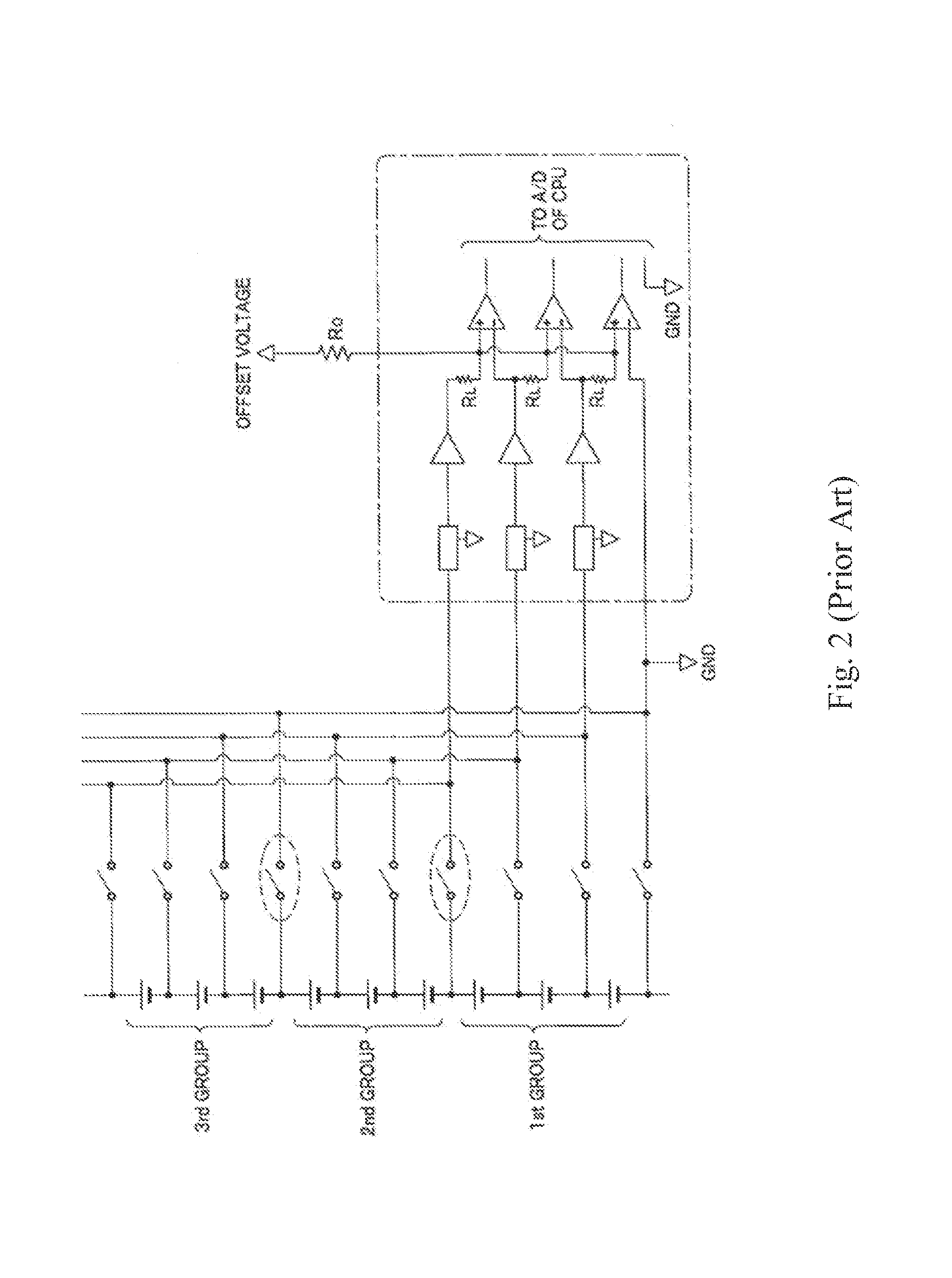
In addition, cost for calibration of analog to digital converters is expensive.
However, they need external components and integrated circuits for voltage transformation.
This brings additional cost.
Meanwhile, self-calibration is not available.
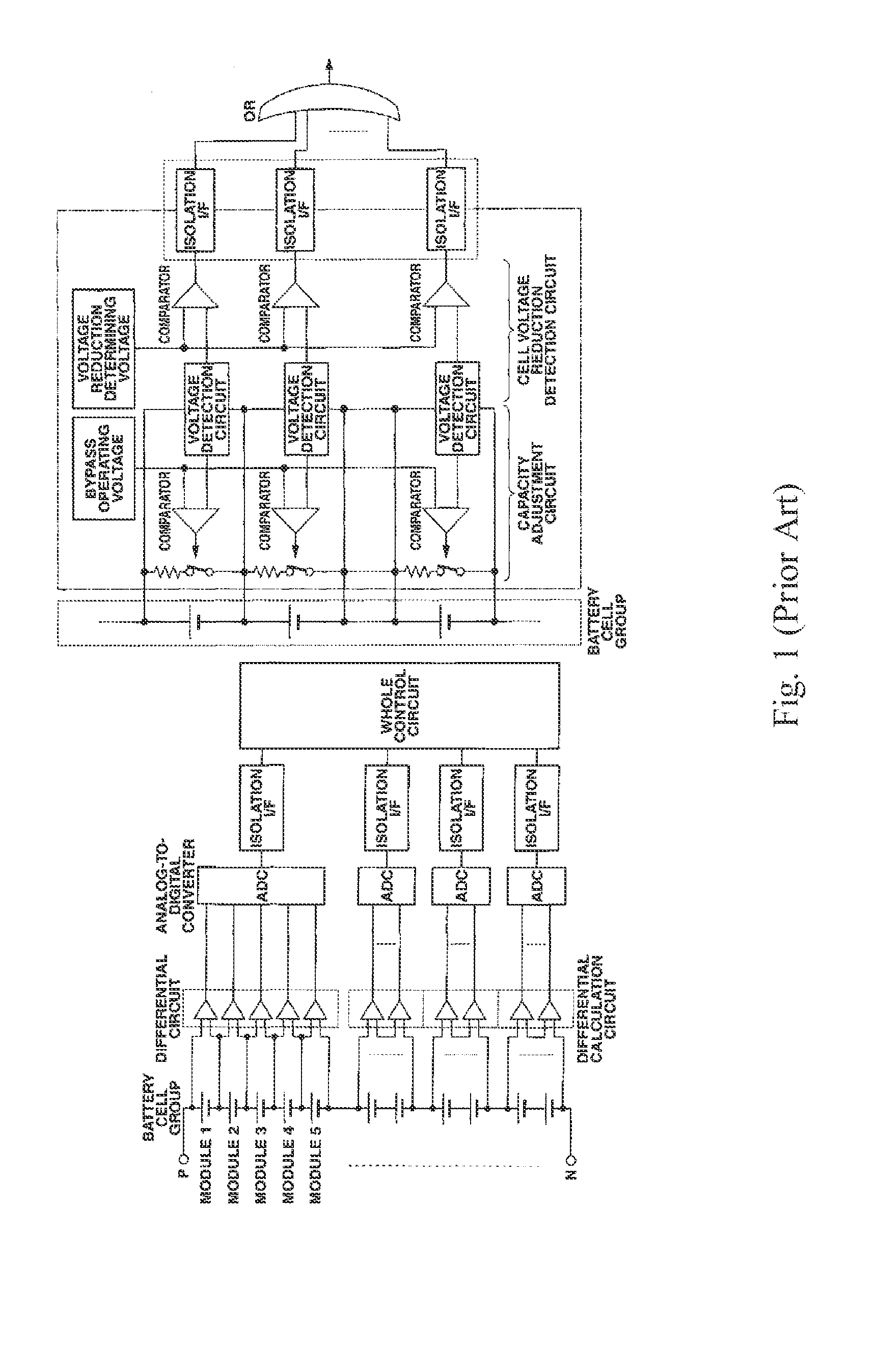
Although calibration problems can be solved by use of a calibrator connected to each battery cells, multiple calibrators will be needed for a battery pack which contains multiple battery cells which would undoubtedly increase the overall manufacturing cost.
Furthermore, if a single calibrator is used for calibration of multiple battery cells, the overall voltage needed for the calibrator would be very high such that the manufacturing cost would increase magnificently.

Method used


Image

  • Cell voltage monitoring and self-calibrating device
  • Cell voltage monitoring and self-calibrating device
  • Cell voltage monitoring and self-calibrating device

Examples


first embodiment

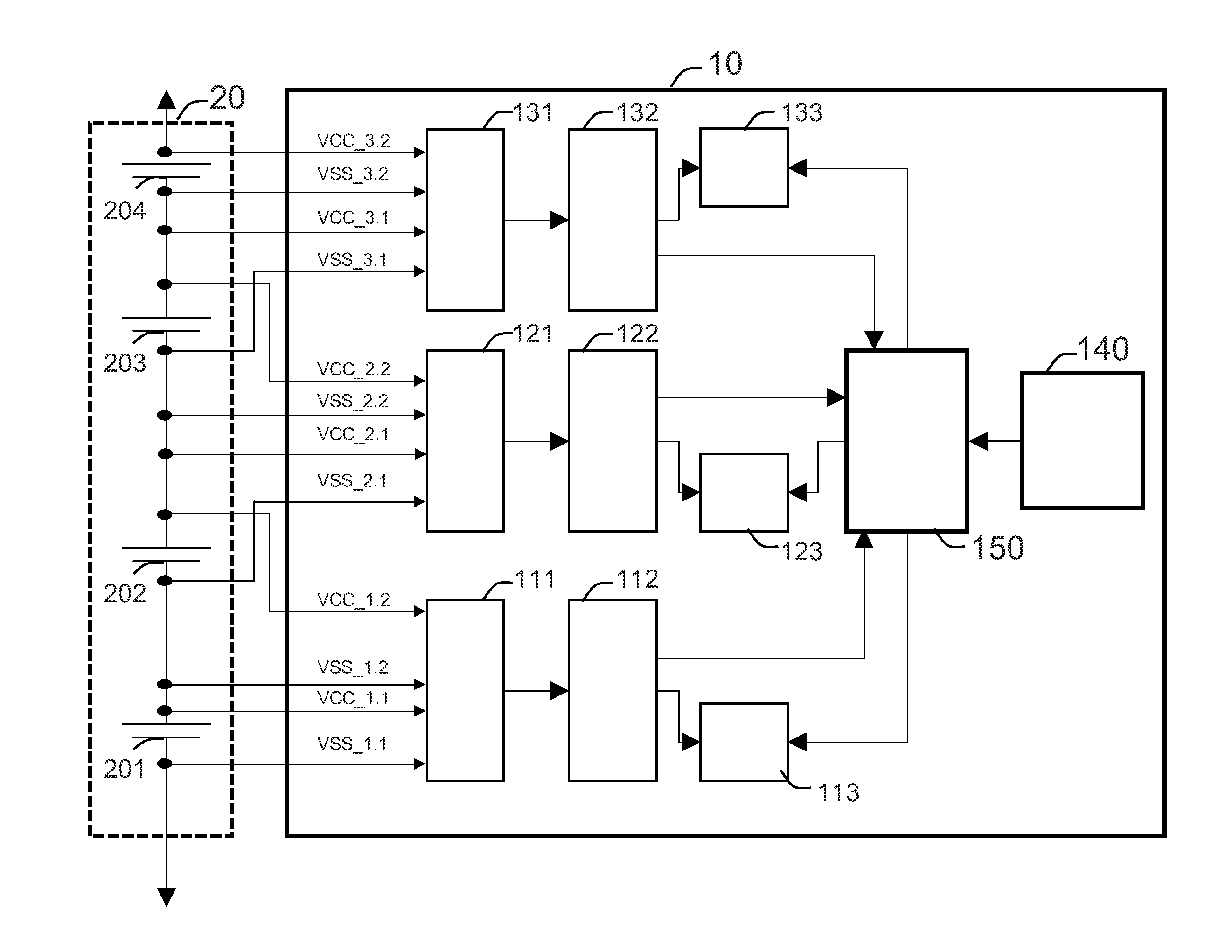
[0034]Please refer to FIG. 3. A first embodiment is illustrated. Please refer to FIG. 3. It shows a layout of a cell voltage monitoring device 10. The cell voltage monitoring device 10 is able to self-calibrate and be applied to a number of battery cells connected in series. In this embodiment, the cell voltage monitoring device 10 is linked to a battery pack 20, having a first battery cell 201, a second battery cell 202 and a third battery cell 203 connected in series sequentially as shown in FIG. 3. All the battery cells mentioned above are rechargeable batteries. Preferably, they are lithium-ion batteries in practice.

[0035]The cell voltage monitoring device 10 includes a first multiplexer 111, a first voltage measurement unit 112, a first compensation unit 113, a second multiplexer 121, a second voltage measurement unit 122, a second compensation unit 123, and a calculating unit 150.

[0036]First, the first multiplexer 111 receives voltages of the first battery cell 201 and the sec...

second embodiment

[0049]The present invention is not limited to be used for measuring a battery pack with only three battery cells. It can also be used for battery packs which include more than three battery cells. Take a battery pack which includes four battery cells as an example.

[0050]Please refer to FIG. 4. The second embodiment is disclosed. Members having like functions will be identified by like reference numerals and overlapping descriptions will be omitted.

[0051]The differences between the first embodiment and the second embodiment are that the battery pack 20 further includes a fourth battery cell 204, and the cell voltage monitoring device 10 further has a third multiplexer 131, a third voltage measurement unit 132 and a third compensation unit 133 in the second embodiment.

[0052]The third multiplexer 131 is connected to the third battery cell 203 and the fourth battery cell 204 in parallel, respectively, and receives voltages of the third battery cell 203 and the fourth battery cell 204 in...


PUM


Abstract

A cell voltage monitoring and self-calibrating device for a plurality of battery cells connected in series is disclosed. The device includes a first voltage measurement unit, a second voltage measurement unit, a first compensation unit, a second compensation unit and a calculating unit. It can measure voltages of each cell in a battery pack which provides power to electric equipment and calibrates itself during measurement.

Description

FIELD OF THE INVENTION[0001]The present invention relates to a cell voltage monitoring and self-calibrating device. More particularly, the present invention relates to a cell voltage monitoring and self-calibrating device for a plurality of battery cells connected in series. The present invention can be applied to measure voltage of each battery in a battery pack for battery driven equipment, such as electric vehicles, electric tools and so on.BACKGROUND OF THE INVENTION[0002]Rechargeable battery is a group of one or more electrochemical cells. They are known as secondary cells because their electrochemical reactions are electrically reversible. Among all kinds of rechargeable batteries, lithium-ion battery (Li-ion battery or LIB) is the most commonly used one. It can be applied to many electric products, such as electric vehicles, electric motorcycles, electric tools, toys and so on. Stable power supply, compact size and recharging ability are the advantages for all applications.[0...

Claims


Application Information

Patent Timeline
Patent Type & Authority Applications(United States)
IPC IPC(8): G01R35/00G06F19/00
CPCG01R35/005G01R31/396
Inventor CHAO, PO YINWANG, CHUAN SHENGCHEN, HUNG WEI
Owner HYCON TECH
Learn More