Electronic nose device

a technology of electronic nose and nose, which is applied in the field of electronic nose devices, can solve the problems of large size, inconvenient home and business applications, and the inability of passive electronic noses to detect air, so as to improve detection precision, reduce the size of passive electronic noses, and simplify the structure of active extraction-type electronic noses.

Inactive Publication Date: 2014-01-23
EPS BIO TECH CORP
View PDF1 Cites 13 Cited by
  • Summary
  • Abstract
  • Description
  • Claims
  • Application Information

AI Technical Summary

Benefits of technology

[0011]An object of the invention is to provide an electronic nose device that can suck air with a stable air current to improve the detection precision.
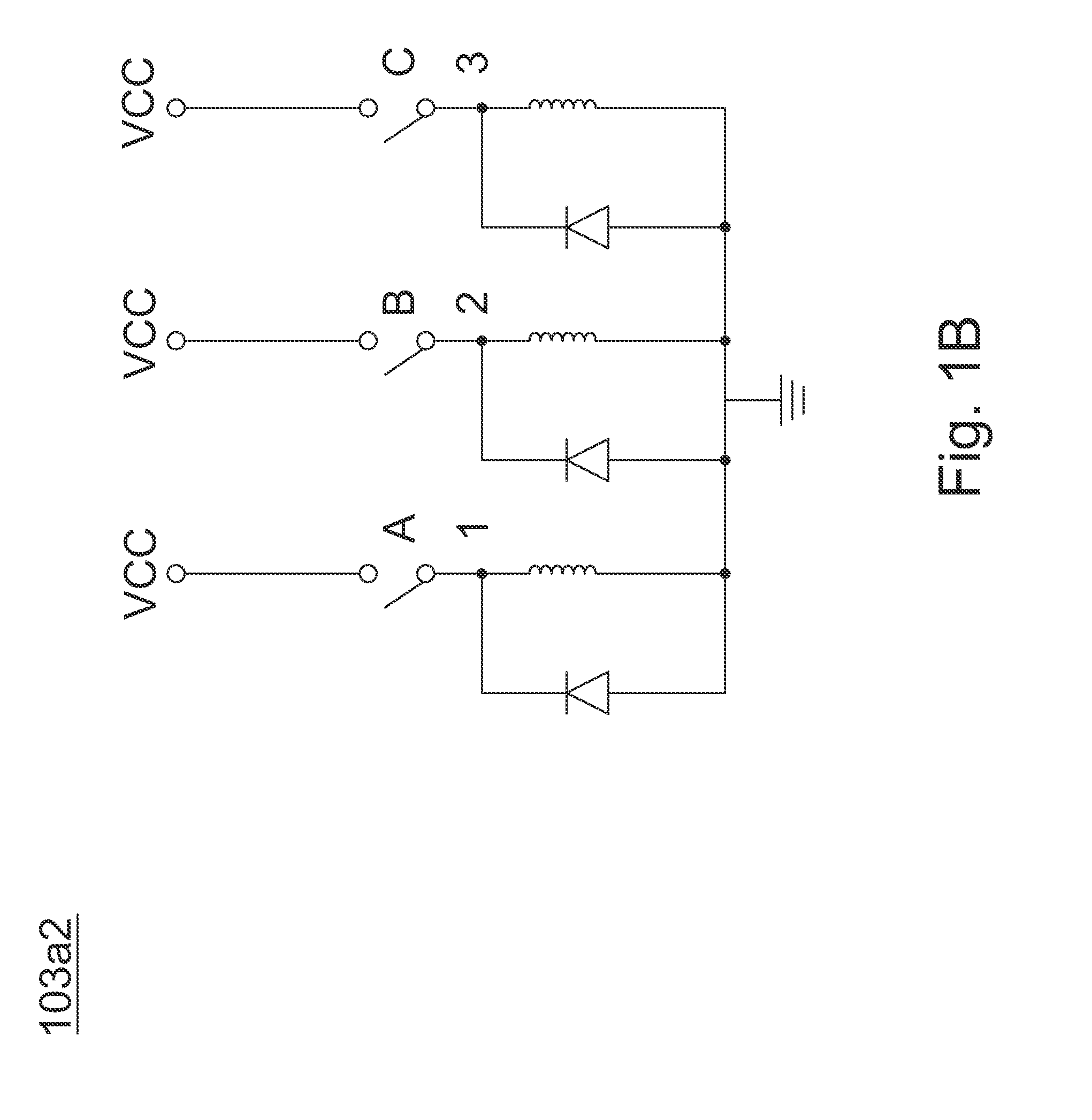
[0012]An electronic nose device of an embodiment of the invention is to improve a fan control circuit of a prior electronic nose using a flow meter. The embodiment of the electronic nose device calculates an air flow rate according to a relation between excitation and back-EMF (back electromotive force) from an operation of a fan module (such as a brushless motor). Therefore the structure of an active-extraction-type electronic nose can be simplified. Thus the size of the active-extraction type electronic nose can be reduced and the application of the electronic nose device can become popular.

Problems solved by technology

Prior electronic noses have been generally applied to many testing and industrial fields so that they have large size and are not suitable for home and business applications.
A passive type electronic nose cannot detect air, such as spontaneous stink from a toilet, since it is not equipped with a pump to pump air in from the outside.

Method used


Image

  • Electronic nose device
  • Electronic nose device
  • Electronic nose device

Examples


Embodiment Construction

[0022]In this specification and the appended claims, some specific words are used to describe specific elements. It should be understood by those who are skilled in the art that some hardware manufacturer may use different names to indicate the same element. In this specification and the appended claims, elements are not differentiated by their names but their functions. As used herein and in the claims, the term “comprising” is inclusive or open-ended and does not exclude additional unrecited elements, compositional components, or method steps. Besides, the term “coupling”, when used herein and in the claims, refers to any direct or indirect connection means. Thus, if the specification describes a first device is coupled to a second device, it indicates that the first device can be directly connected (via signal connection, including electrical connection, wireless transmission, optical transmission, etc.) to the second device, or be indirectly connected to the second device via an...


PUM

PropertyMeasurementUnit
air currentaaaaaaaaaa
piezoelectricaaaaaaaaaa
flow rateaaaaaaaaaa

Abstract

An electronic nose device is disclosed in an embodiment of the invention. The electronic nose device includes a fan module, a gas molecule sensor module, a control unit and an output unit. The fan module is used to pump air actively to the gas molecule sensor module. The gas molecule sensor module detects the air pumped into by the fan module. The gas molecule sensor module at least includes a gas molecule sensor which is covered with a compound. The compound is used to combine preset gas molecules. The control unit controls the fan module to suck air into the electronic nose device. Then the fan module transmits an air current to the gas molecule sensor module to generate a detected data. The output unit calculates the detected data to generate a calculation result and outputs an indicating signal to an operator or compatible host computer according to the calculation result.

Description

[0001]This application claims the benefit of the filing date of Taiwan Application Ser. No. 101126266, filed on Jul. 20, 2012, the content of which is incorporated herein by reference.BACKGROUND OF THE INVENTION[0002]1. Field of the Invention[0003]The invention relates to an electronic device, and more particularly, to an electronic nose device.[0004]2. Description of the Related Art[0005]Prior electronic noses have been generally applied to many testing and industrial fields so that they have large size and are not suitable for home and business applications.[0006]Some small electronic noses are separated into a gas storage type (TW patent No. 537879), a passive type (TW patent No. M305669) and a series flow meter type (TW publication No. 201219009).[0007]A gas storage type electronic nose needs to set up a storage space and a complicated air pipe system to reach a purpose of generating a stable air current for detection.[0008]A passive type electronic nose cannot detect air, such ...

Claims


Application Information

Patent Timeline
Patent Type & Authority Applications(United States)
IPC IPC(8): G01N33/00
CPCG01N33/0027Y10T436/11Y10T436/255
Inventor TIAN, JUN-HAOCHEN, JIAN-HUACHU, CHI-ZUOHO, WEI-JENKANG, LI-JINWANG, YU-LUNLI, MENG-ERH
Owner EPS BIO TECH CORP
Why Eureka
Try Eureka