Structure monitoring
- Summary
- Abstract
- Description
- Claims
- Application Information
AI Technical Summary
Benefits of technology
Problems solved by technology
Method used
Image
Examples
first embodiment
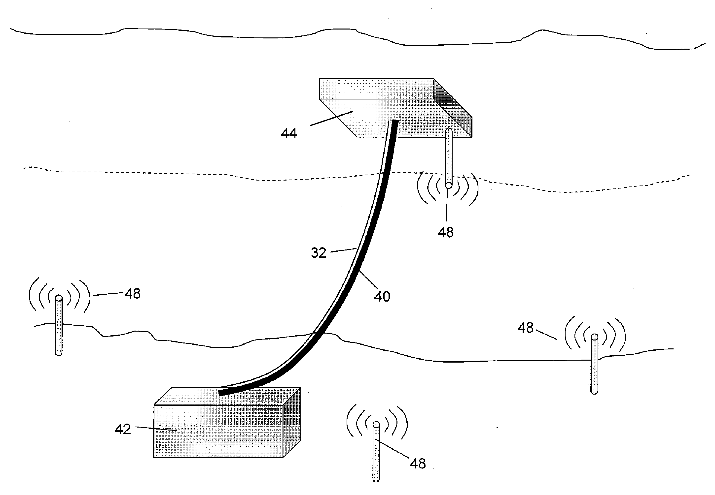
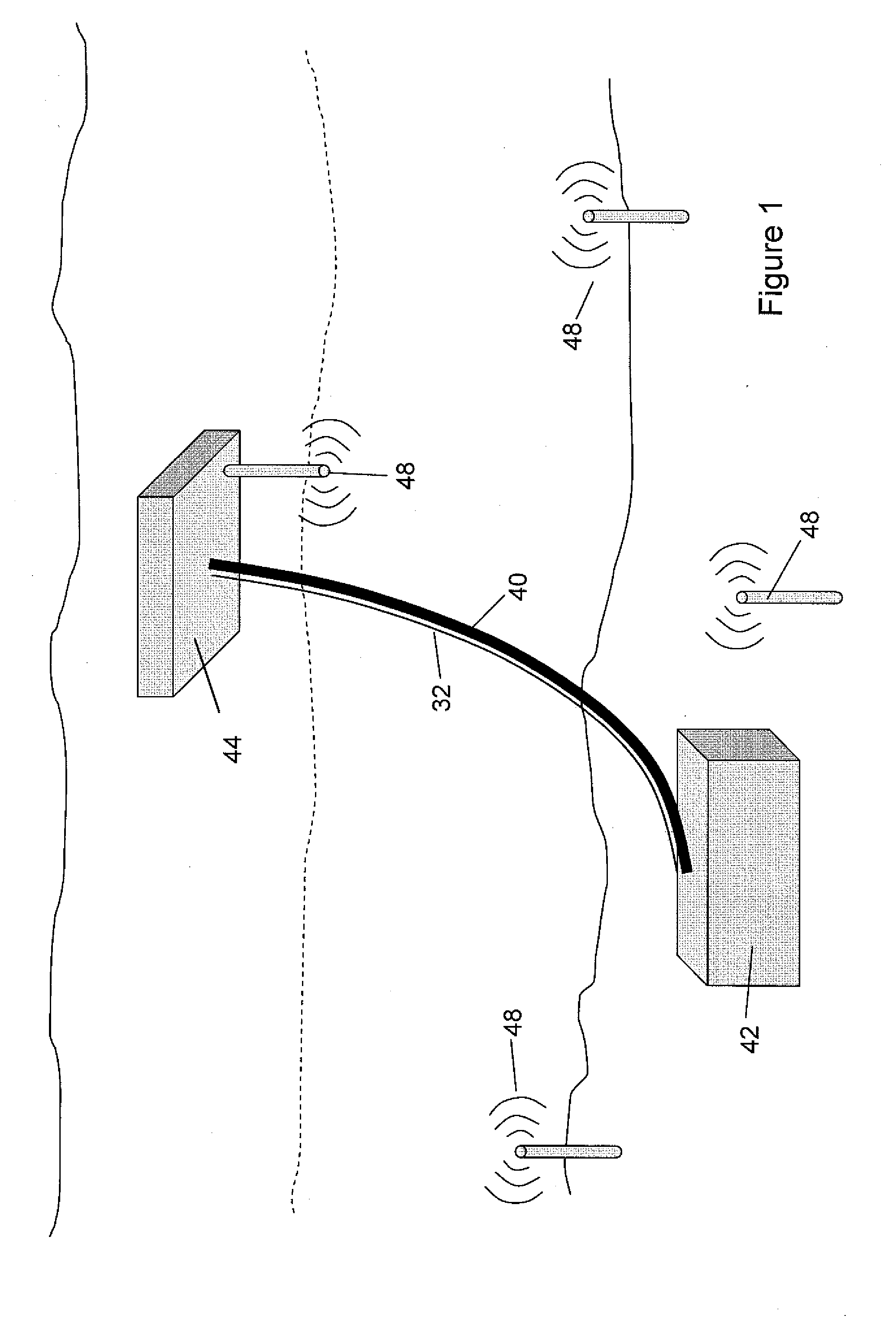
[0066]FIG. 3 illustrates the operating environment of a Here, fiber 32 attached to or otherwise related in a known manner to a subsea riser (not shown) extends from surface vessel 44 to seafloor installation 42. The fiber 32 forms part of a DAS, as described above, that is able to sense an incident vibro acoustic field with a spatial resolution of approximately 1 m. Hence, an acoustic sensor 462 is formed approximately every 1 m along fiber 32, to give n acoustic sensors along the length of fiber 32.
[0067]Also provided are x acoustic sources Xn (48), with four such sources being shown in FIG. 3. Each acoustic source is at a known location, and emits an identifiable acoustic signal, for example at a specific, known, frequency, or of a particular pattern.
[0068]In a first embodiment of the invention, each sensor 462 is treated individually, and a respective location found for a particular sensor without reference to positions found for other sensors on the fibre. FIG. 4 illustrates th...
third embodiment
[0075]FIGS. 6 and 7 illustrate the concept of the Specifically, contiguous groups of sensors 462 along the fiber 32 are grouped together into a virtual small line array sensor 62. An incident acoustic wave incident on the line array sensor 62 will cause an output from each of the sensors at different times, dependent on the angle of incidence of the wave. Hence, as shown in FIG. 6, an incident wave 64 incident on line array 62 at the angle shown will first cause a signal from sensor 622 , followed by sensor 624, 628, and finally 630. Moreover, the time delay 8 between each sensor being triggered is a cosine function of the direction of travel of the wave, whereby the angle of incidence of the wave can be determined from the order in which the sensors give an output and the time delay between sensor outputs along the array. In this respect, it is assumed that the array size is small enough so as to be considered to be in the far field of the incident wave.
[0076]FIGS. 8 and 9 illustr...
PUM
 Abstract
Description
Claims
Application Information
 - R&D
- Intellectual Property
- Life Sciences
- Materials
- Tech Scout
- Unparalleled Data Quality
- Higher Quality Content
- 60% Fewer Hallucinations
Browse by: Latest US Patents, China's latest patents, Technical Efficacy Thesaurus, Application Domain, Technology Topic, Popular Technical Reports.
© 2025 PatSnap. All rights reserved.Legal|Privacy policy|Modern Slavery Act Transparency Statement|Sitemap|About US| Contact US: help@patsnap.com


