
Method and Device for Adjusting Demodulation Pilot Frequency in Wireless Communication System

Active Publication Date: 2014-01-16
BEIJING NUFRONT MOBILE MULTIMEDIA TECH
View PDF8 Cites 31 Cited by
  • Summary
  • Abstract
  • Description
  • Claims
  • Application Information

AI Technical Summary

Benefits of technology

The present invention provides a method and device for adjusting pilots in a wireless communication system to improve system performance. By adapting the pilot configuration based on the device capabilities, system requirements, and the wireless propagation environment, the method and device can ensure reliable transmission and increase the average system capacity. This results in better system performance and better user experience.

Problems solved by technology

Using pilot in fixed pattern is not conducive to its adaption to a complex, and changing mobile communication environment, and further causes certain loss in the system capacity.
Thus, the fixed pilot can't adapt to environmental change.

Method used

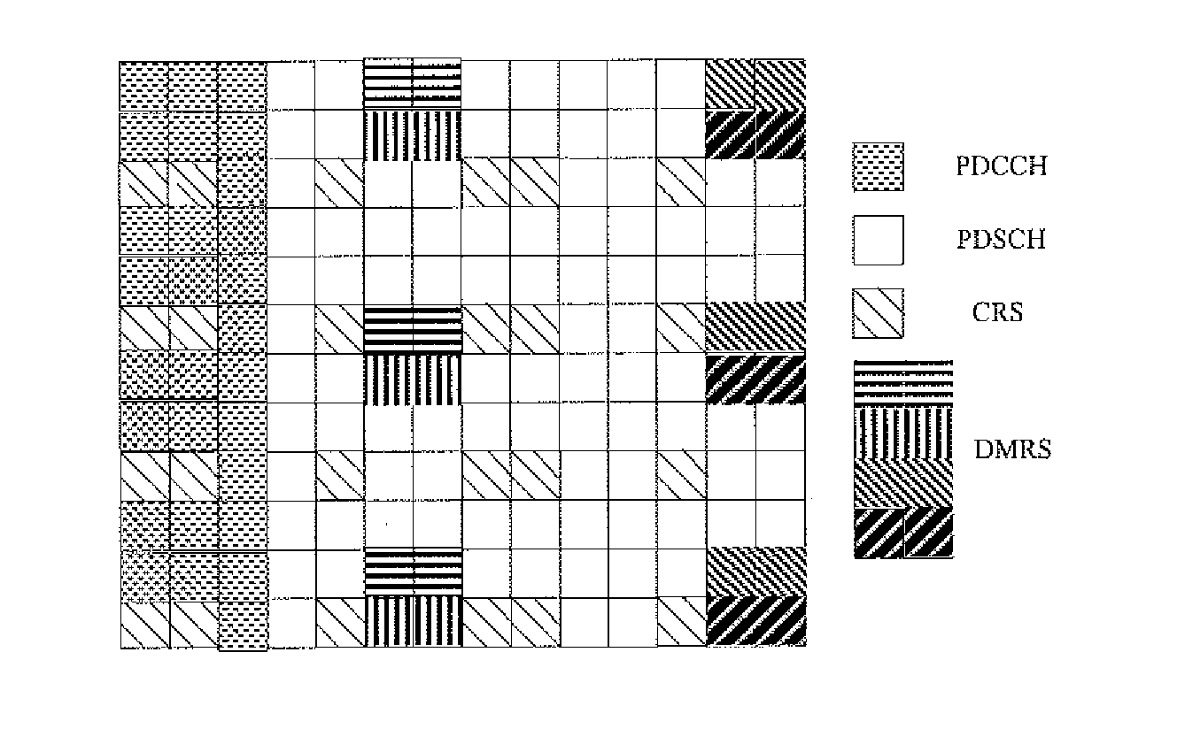
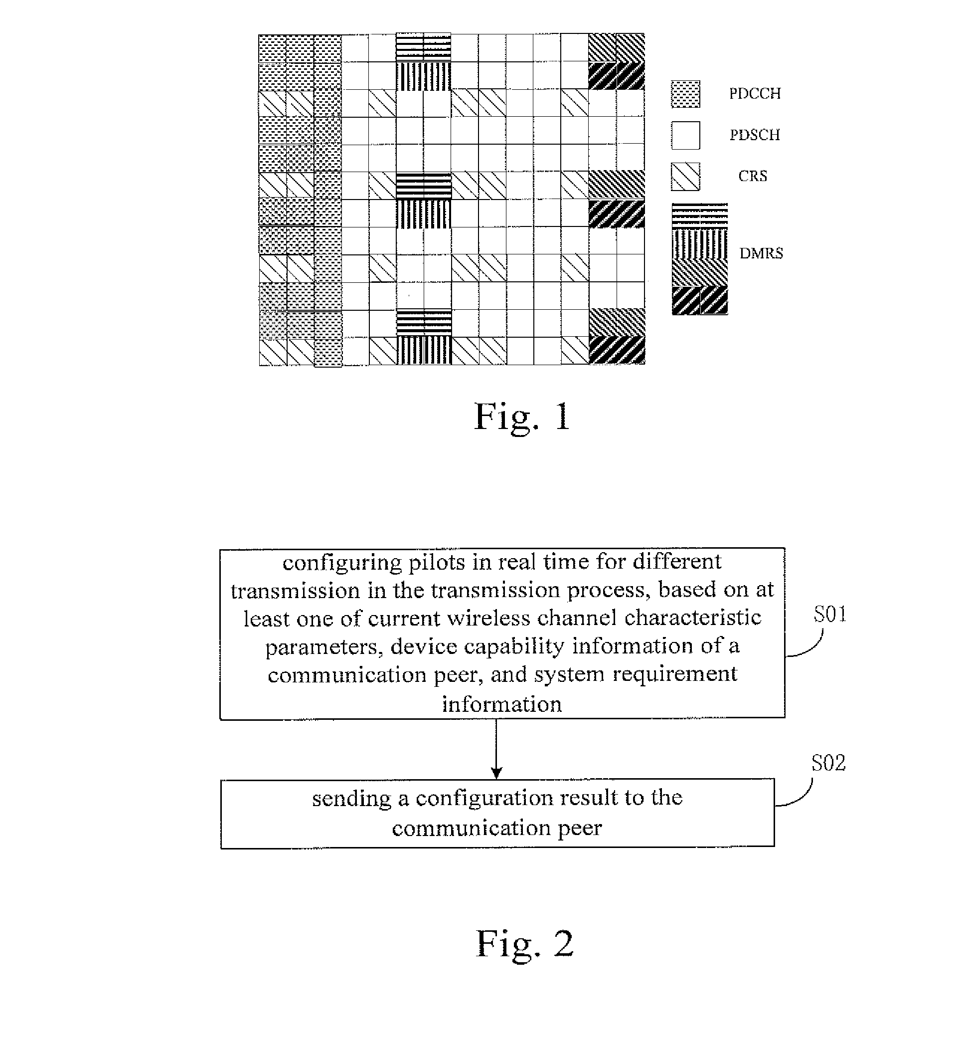

Image

  • Method and Device for Adjusting Demodulation Pilot Frequency in Wireless Communication System
  • Method and Device for Adjusting Demodulation Pilot Frequency in Wireless Communication System
  • Method and Device for Adjusting Demodulation Pilot Frequency in Wireless Communication System

Examples


first application example

A First Application Example

[0131]In the present application example, a CAP configures pilots based on current wireless channel characteristic parameters.

[0132]The CAP may obtain the current wireless channel characteristic parameters by many ways, for example, by channel measuring, or by information interacting with the STA.

[0133]In this application example, it is assumed that a station STA1 is in a moving state and stations STA2 and STA0 are rest.

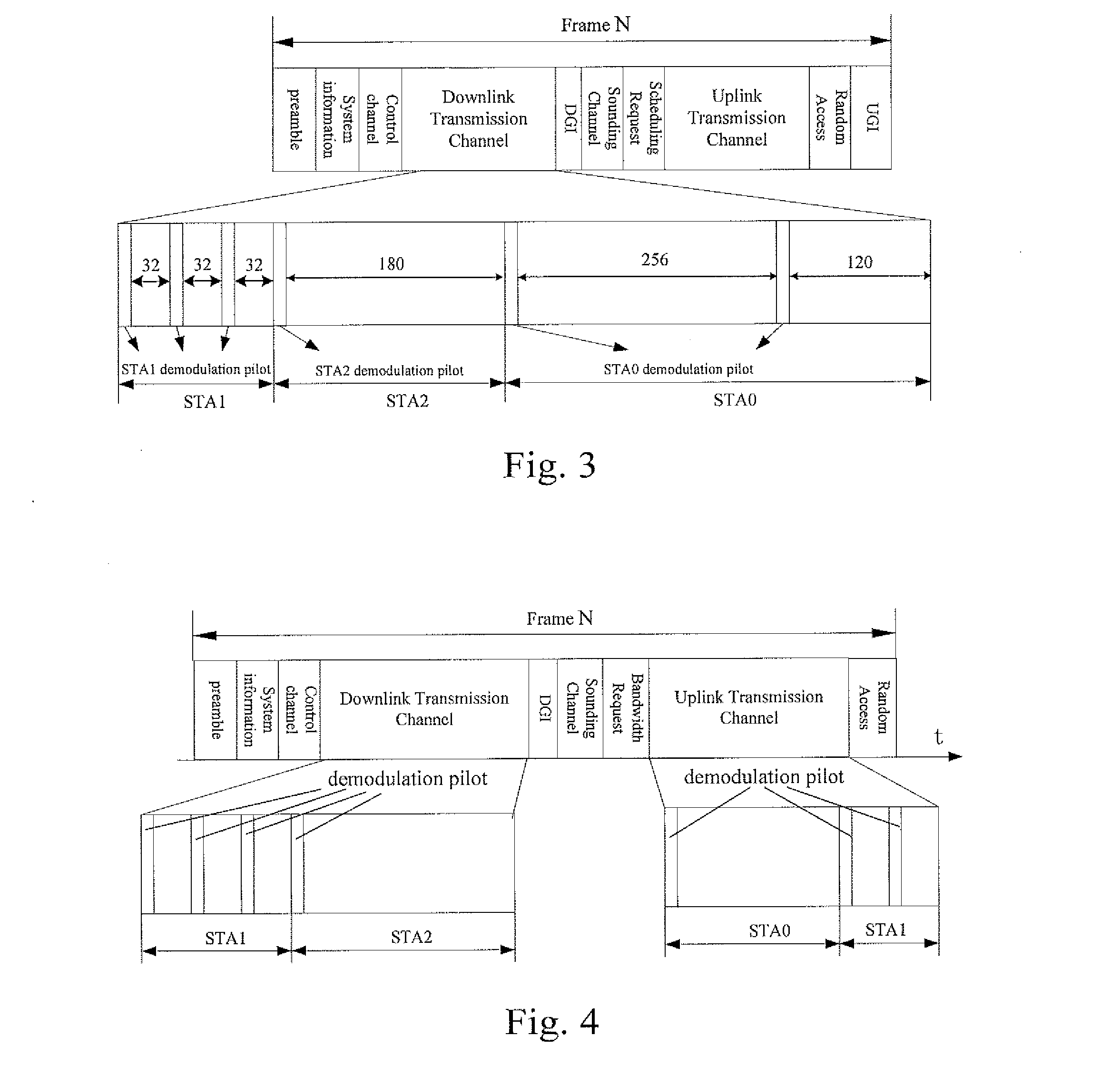
[0134]The CAP may obtain correlation time of the stations STA0, STA1, and STA2 by channel measurement (e.g., Doppler spectral measurements), and obtain correlation bandwidths of the stations STA0, STA1, and STA2 through channel measurements (such as power delay spectral measurement). Specifically, the wireless channel correlation time of the moving station STA1 is less than that of the stations STA0 and STA2 in the rest state, and the wireless channel correlation bandwidth of the moving station STA1 is less than that of the stations STA0 an...

second application example

A Second Application Example

[0148]In the present application example, the CAP configures the pilot based on the device capability information of the communication peer.

[0149]The CAP interacts with stations STA1 and STA2 for device capabilities. To overcome the affection of a synchronization error on OFDM data symbol detection, the CAP has to transmit a set of pilots periodically, to correct phase offset accumulation caused by the synchronization error. Pilots configured for the station SATI are contained in a downlink transmission channel in the transmission frame structure as shown in FIG. 4.

[0150]The CAP may acquire the device capability information of the communication peer by various ways, for example, by capability negotiating with the STA.

[0151]Assuming that the station STA1 is a low-end device with significant sampling synchronization error and frequency synchronization error. The station STA2 is a high-end device with small sampling synchronization error and frequency synchr...

third application example

A Third Application Example

[0161]In the present application example, the pilot is configured according to the system requirement information, which is known to the CAP.

[0162]In the wireless communication system, the station STA1 is closer to the CAP, while the station STA2 is farther to the CAP.

[0163]In this application example, the pilot is configured based on the modulation order and the code rate, respectively.

[0164]During the downlink transmission, the station STA1 is closer to the CAP, so that a link propagation loss is small and the power of a signal received by the station STA1 is high, thus a high-order modulation scheme such as 64 QAM may be employed for data transmission. The station STA2 is farther from the CAP, so that the link propagation loss is relative large and the power of a signal received by the station STA2 is low, thus a low-order modulation scheme such as QPSK is employed for data transmission. Since the high-order modulation is more sensitive to a channel fas...


PUM


Abstract

Disclosed is a method for configuring a pilot frequency in a wireless communication system, comprising: on the basis of at least one item among a current wireless channel characteristic parameter, device capability information of a correspondent node, and system requirement information, configuring in real-time a pilot frequency for different transmissions during a transmission process; and transmitting the configuration result to the correspondent node. Also disclosed is a corresponding device for configuring the pilot frequency. The present invention allows for configuration in real-time of the pilot frequency. This facilitates improved transmission reliability and guaranteed communication quality, and reduces pilot frequency overhead, and at the same time, is applicable in additional number of channel environments and application scenarios.

Description

CROSS-REFERENCE TO RELATED APPLICATION[0001]This application claims the priority of Chinese Application No. 201110074598.5 filed on Mar. 25, 2011 and titled “METHOD AND SYSTEM FOR ADJUSTING DEMODULATION PILOT IN WIRELESS COMMUNICATION SYSTEM”, which is incorporated herein by reference in its entirety.[0002]This application claims the priority of Chinese Application No. 201110083209.5 filed on Apr. 02, 2011 and titled “METHOD AND SYSTEM FOR ADJUSTING DEMODULATION PILOT IN WIRELESS COMMUNICATION SYSTEM”, which is incorporated herein by reference in its entirety.[0003]This application claims the priority of Chinese Application No. 201110130194.3 filed on May 19, 2011 and titled “COMMUNICATION SYSTEM”, which is incorporated herein by reference in its entirety.FIELD OF THE INVENTION[0004]The present invention relates to the wireless communication technology field, particularly, relates to a method and device for configuring a pilot in a wireless communication system.BACKGROUND OF THE INV...

Claims


Application Information

Patent Timeline
IPC IPC(8): H04L5/00
CPCH04L5/0048H04L5/001H04L5/0064H04L5/0085H04L1/0026H04L1/0027H04L1/0067H04L1/0068H04L5/0023H04L5/0037H04L5/0046H04L27/2626H04L27/2647H04W52/146H04W52/226H04W52/242H04L27/2657H04L5/0051H04B7/24H04B7/005
Inventor BAO, DONGSHANWANG, JINGLIU, SHENFAYAN, ZHIGANGWANG, FEIFEI
Owner BEIJING NUFRONT MOBILE MULTIMEDIA TECH
Learn More