Compound modulation transfer function for laser surgery and other optical applications

a transfer function and laser surgery technology, applied in the field of goal functions or visual function diagnostic metrics, can solve the problems of loss of ability to focus on objects at near distances, limited ability to change shape, and loss of elastic properties of crystalline lenses, etc., and achieve the effect of mitigating presbyopia

Active Publication Date: 2014-01-16
AMO MFG USA INC
View PDF0 Cites 6 Cited by
  • Summary
  • Abstract
  • Description
  • Claims
  • Application Information

AI Technical Summary

Benefits of technology

This patent is about a system that can create a special optical surface shape to improve vision for a particular patient. The system takes into account the patient's needs and the shape of their eye, using a special tool called a pupilometer. The system calculates a prescription for the patient that provides a desired power for the eye based on the pupil size. This special optical surface shape helps to improve the patient's vision when looking at objects at different distances, which can help to reduce the effects of presbyopia.

Problems solved by technology

There may also be a loss in the ability to focus on objects at near distances.
By the age of 65 years, the crystalline lens has often lost almost all elastic properties and has only limited ability to change shape.
Unfortunately, with monovision the individual may not clearly see objects that are intermediately positioned because the object is out-of-focus for both eyes.
Also, an individual may have trouble seeing with only one eye, or may be unable to tolerate an imbalance between their eyes.
Problems remain with such techniques, however, such as inconsistent and unpredictable outcomes.
Many of these ablation profiles can provide a single excellent focus of the eye, yet they do not provide an increased depth of focus such that optimal distance acuity, optimal near acuity, and acceptable intermediate acuity occur simultaneously.
Shapes have been proposed for providing enhanced distance and near vision, yet current approaches do not provide ideal results for all patients.
However, many of the currently used goal functions are difficult and cumbersome to implement with current clinical methods, and are insufficient in utilizing currently available clinical data and in providing guidance to the administration and diagnosis of reported visual difficulties.

Method used


Image

  • Compound modulation transfer function for laser surgery and other optical applications
  • Compound modulation transfer function for laser surgery and other optical applications
  • Compound modulation transfer function for laser surgery and other optical applications

Examples


Embodiment Construction

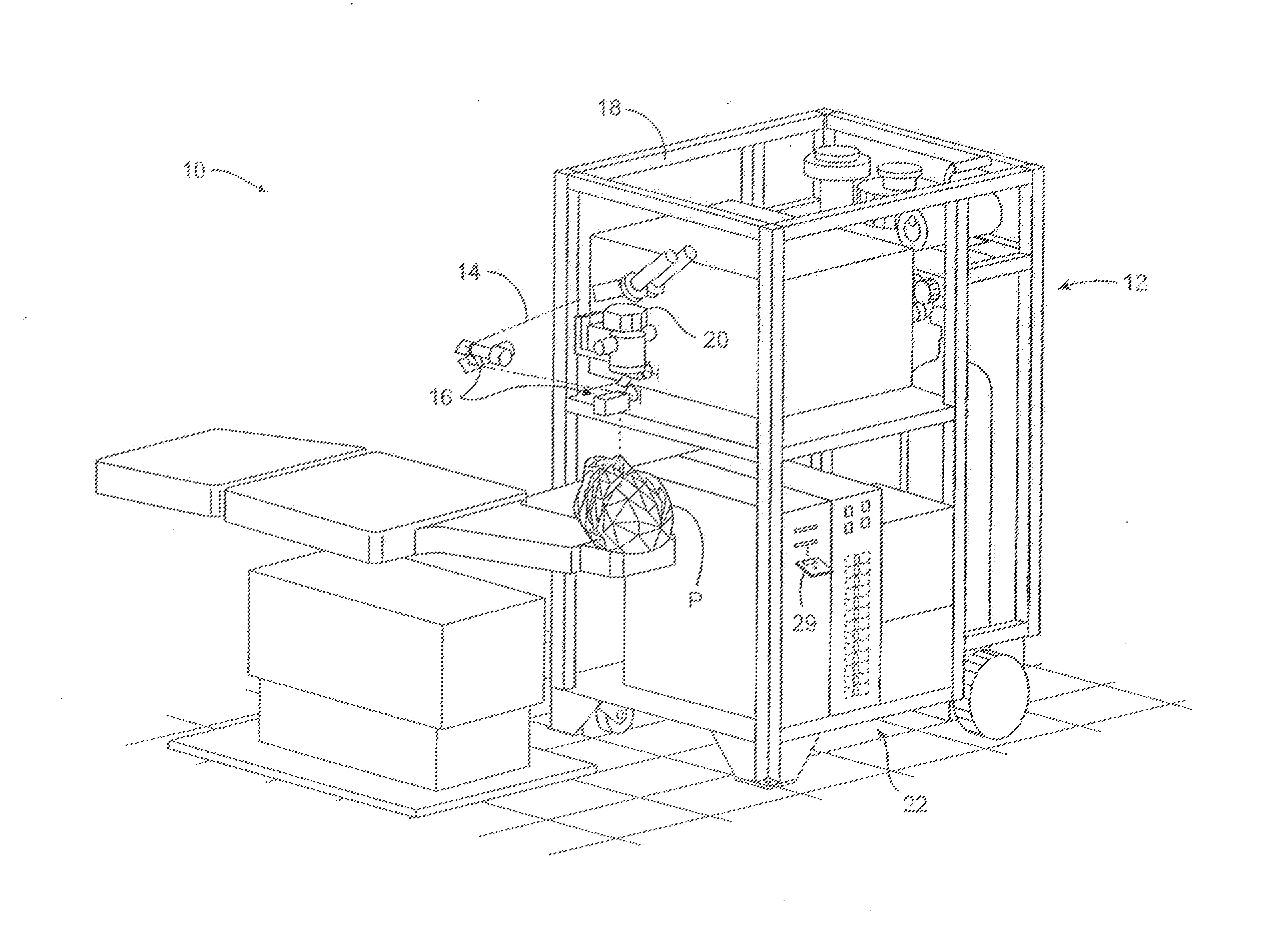
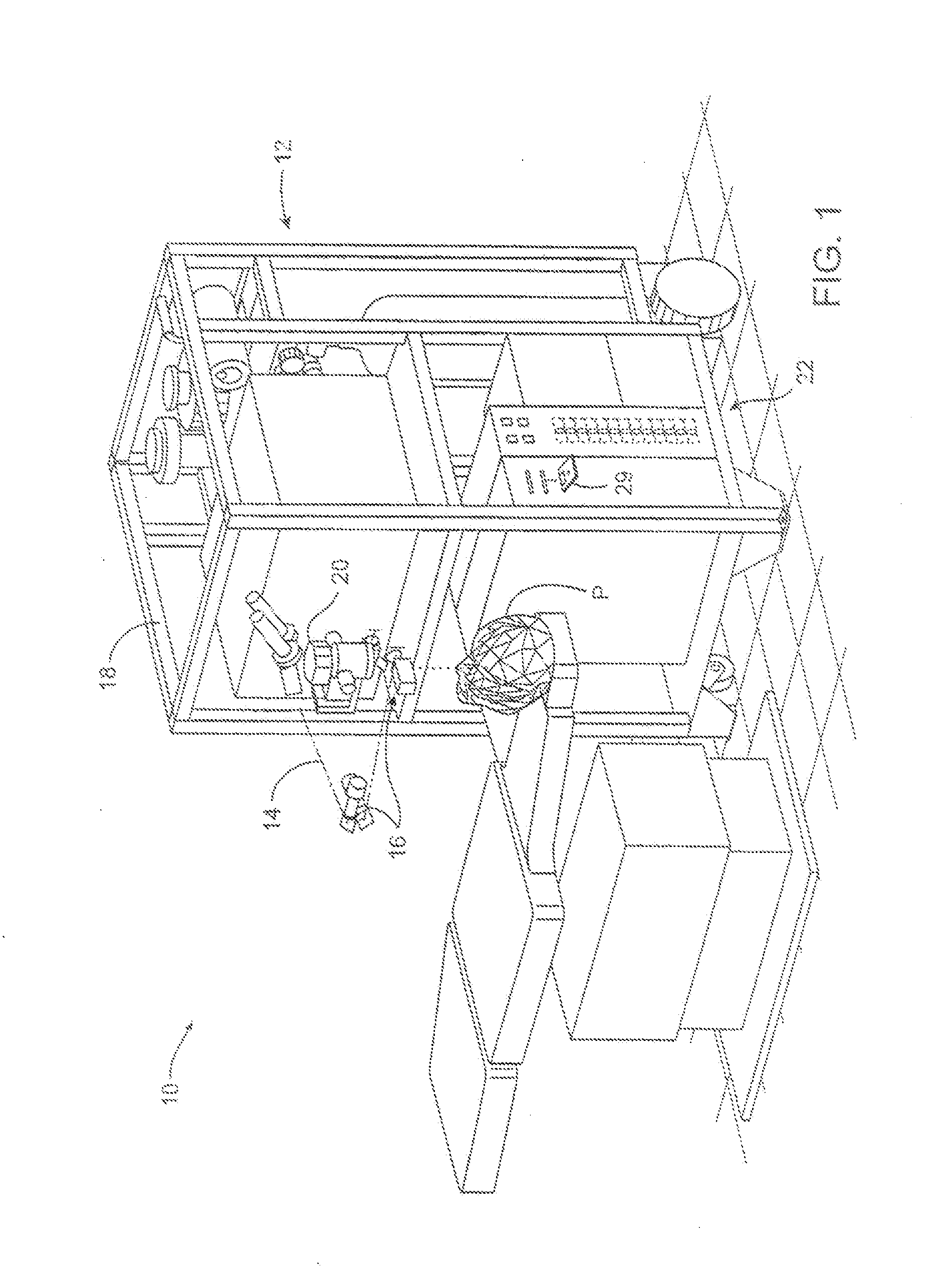
[0114]Although the methods, devices, and systems of the present invention are described primarily in the context of a laser eye surgery system, it should be understood that the techniques of the present invention may be adapted for use in other eye treatment procedures and systems such as contact lenses, intra-ocular lenses, radial keratotomy, collagenous corneal tissue thermal remodeling, removable corneal lens structures, glass spectacles, corneal ring implants, and the like.

[0115]Turning now to the drawings, FIG. 1 illustrates a laser eye surgery system 10 of the present invention, including a laser 12 that produces a laser beam 14. Laser 12 is optically coupled to laser delivery optics 16, which directs laser beam 14 to an eye E of patient P. A delivery optics support structure (not shown here for clarity) extends from a frame 18 supporting laser 12. A microscope 20 is mounted on the delivery optics support structure, the microscope often being used to image a cornea of eye E.

[0...


PUM


Abstract

Methods, devices, and systems establish an optical surface shape that mitigates or treats a vision condition in a patient. An optical surface shape for a particular patient can be determined using a set of patient parameters for the specific patient by using a compound modulation transfer function (CMTF). The compound modulation transfer function can include a combination of modulation transfer functions (MTF's) at a plurality of distinct frequencies.

Description

CROSS-REFERENCES TO RELATED APPLICATIONS[0001]This application is a continuation-in-part of U.S. patent application Ser. No. 13 / 184,515, filed Jul. 16, 2011 (now U.S. Pat. No. 8,342,686), which is a continuation-in-part of U.S. patent application Ser. No. 12 / 955,270, filed Nov. 29, 2010 (now U.S. Pat. No. 8,029,137), which is a continuation of U.S. patent application Ser. No. 12 / 329,743, filed Dec. 8, 2008 (now U.S. Pat. No. 7,862,170), which is a continuation of U.S. patent application Ser. No. 11 / 948,475, filed. Nov. 30, 2007 (now U.S. Pat. No. 7,475,986), which is a continuation of U.S. patent application Ser. No. 10 / 911,400 filed Aug. 3, 2004 now U.S. Pat. No. 7,320,517), which is a continuation-in-part of U.S. patent application Ser. No. 10 / 738,358 filed Dec. 5, 2003 (now U.S. Pat. No. 7,293,873), which claims priority from U.S. Patent Application Nos. 60 / 519,885 filed Nov. 13, 2003; 60 / 468,387 filed May 5, 2003; 60 / 468,303 filed May 5, 2003; and 60 / 431,634 filed Dec. 6, 2002. ...

Claims


Application Information

Patent Timeline
Patent Type & Authority Applications(United States)
IPC IPC(8): A61B3/02A61F2/16G02C7/02
CPCA61B3/02G02C7/028A61F2/16A61B3/0025A61F9/00808A61B3/0016
Inventor DAI, GUANG-MING
Owner AMO MFG USA INC
Why Eureka
Try Eureka