Capacitive touch control sensor

a capacitive touch control and sensor technology, applied in the field of can solve the problems of high production cost and complex manufacturing process of conventional multi-layer capacitive touch control sensors b>1/b>, and achieve the effects of reducing manufacturing costs, reducing production costs, and increasing touch sensing area

Inactive Publication Date: 2014-01-16
J TOUCH CORPORATION
View PDF5 Cites 1 Cited by
  • Summary
  • Abstract
  • Description
  • Claims
  • Application Information

AI Technical Summary

Benefits of technology

The present patent is about a capacitive touch control sensor arrangement that solves manufacturing complexity issues. It is single-layered, has a relatively larger screen on electronic products, and increases touch sensing area and precision level. The electrodes are in the shape of "Y" with slanting extensions and non-linear patterns. The electrode wires are arranged in a non-linear pattern. The electrodes and wires are made of transparent conductive material that does not occupy additional display regions, increasing the touch sensing area on the final product. These technical features result in a lower manufacturing cost and lighter product volume, and increased touch sensing area and precision level.

Problems solved by technology

As can be seen, the manufacture process of the conventional multilayer capacitive touch control sensor 1 is complex and the production cost is high.

Method used


Image

  • Capacitive touch control sensor
  • Capacitive touch control sensor
  • Capacitive touch control sensor

Examples


Embodiment Construction

[0015]The aforementioned illustrations and following detailed descriptions are exemplary for the purpose of further explaining the scope of the present disclosure. Other objectives and advantages related to the present disclosure will be illustrated in the subsequent descriptions and appended drawings.

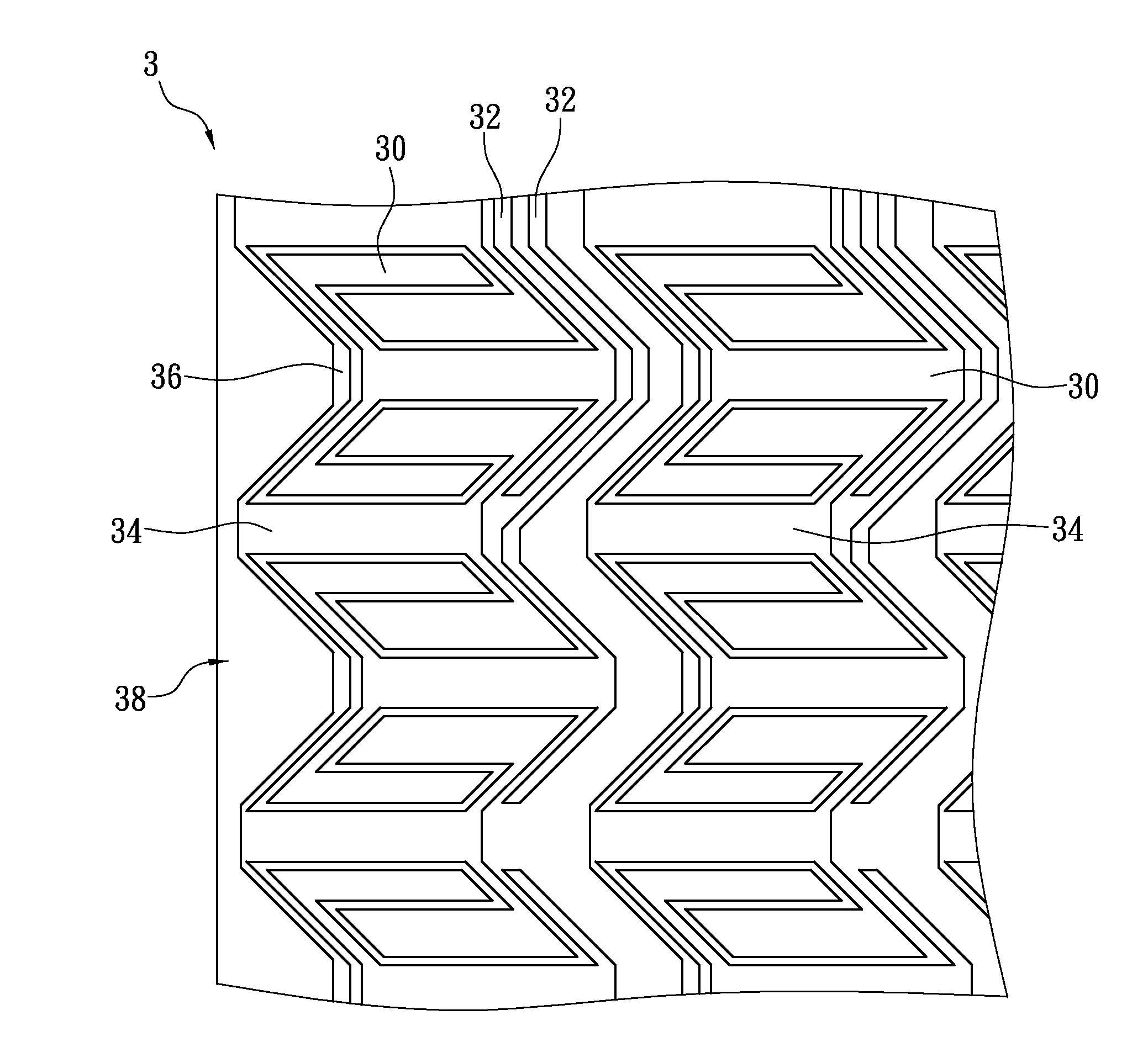
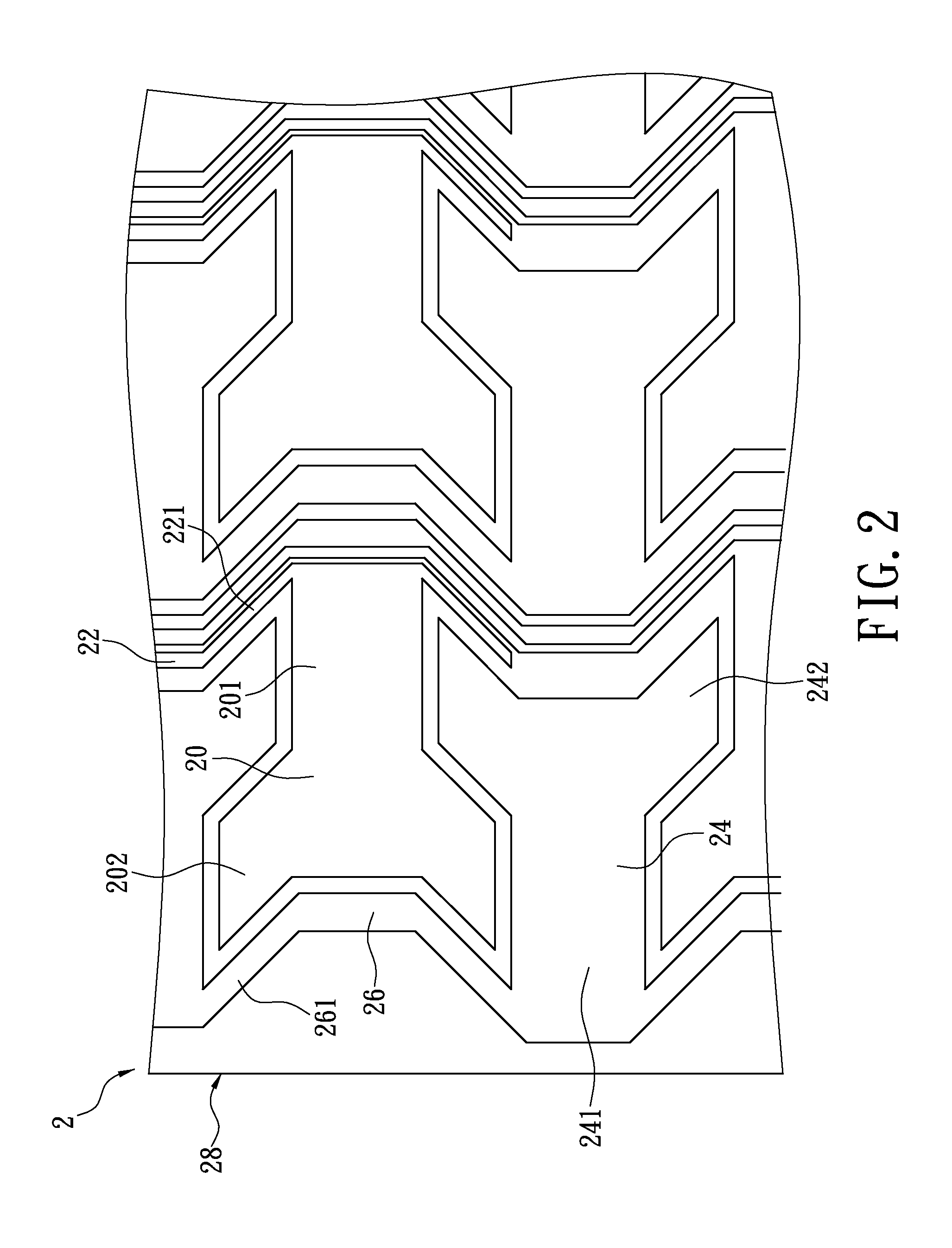
[0016]FIG. 2 shows a perspective view of an embodiment of a capacitive touch control sensor. The capacitive touch control sensor 2 includes a plurality of first electrodes 20, a plurality of first electrodes wire 22, a plurality of second electrodes 24 and a plurality of second electrode wires 26. The first and second electrodes 20, 24 together with the first and second electrode wires 22, 26 are made of a visibly transparent conductive material. The visibly transparent conductive material can be selected from the following: indium tin oxide (ITO), indium zinc oxide, aluminum doped zinc oxide, nanosilver, nanocopper, conductive polymer, carbon nanotube, graphene, silver bromide (AgBr),...


PUM


Abstract

The present disclosure provides a capacitive touch control sensor, including a plurality of first and second electrodes, a plurality of first and second electrode wires. The first and second electrodes are aligned at predetermined interval. Each of the first electrode wires connects to one of the first electrodes while each of the second electrode wires connects to more than one of the second electrodes. The first and second electrodes are alternatively disposed so as to reduce manufacturing cost and achieve lower structural profile.

Description

BACKGROUND[0001]1. Technical Field[0002]The present disclosure relates to a capacitive touch control sensor; in particular, to a single-layered capacitive touch control sensor.[0003]2. Description of Related Art[0004]FIG. 1 shows a top view of a conventional capacitive touch control sensor 1 having a multilayered structure that requires multiple fabrication processes. In a first fabrication process, a plurality rows of first axial electrode blocks 10, a plurality rows of first axial wires 11, and a plurality rows of separately and adjacently arranged second axial electrode blocks 12 are disposed on a substrate surface of the capacitive touch control sensor 1. The first axial wire 11 interconnects each row of the first axial electrode blocks 10 along a first axial direction, and the second axial electrode blocks 12 are separately interposed between each two adjacent rows of the first axial electrode bocks 10 on either side of the first axial wire 11, respectively. In a subsequent sec...

Claims


Application Information

Patent Timeline
Patent Type & Authority Applications(United States)
IPC IPC(8): G06F3/044
CPCG06F3/0443G06F3/0446G06F3/0448G06F2203/04111G06F3/0447
Inventor YEH, YU-CHOUNI, JUI-MINGLAI, PING-HSUJAN, HSIAO-SHUNWU, CHENG-HSIUNG
Owner J TOUCH CORPORATION
Why Eureka
Try Eureka