Conduit sensor device with magnetic shunt and process for modifying a magnetic field
- Summary
- Abstract
- Description
- Claims
- Application Information
AI Technical Summary
Benefits of technology
Problems solved by technology
Method used
Image
Examples
Embodiment Construction
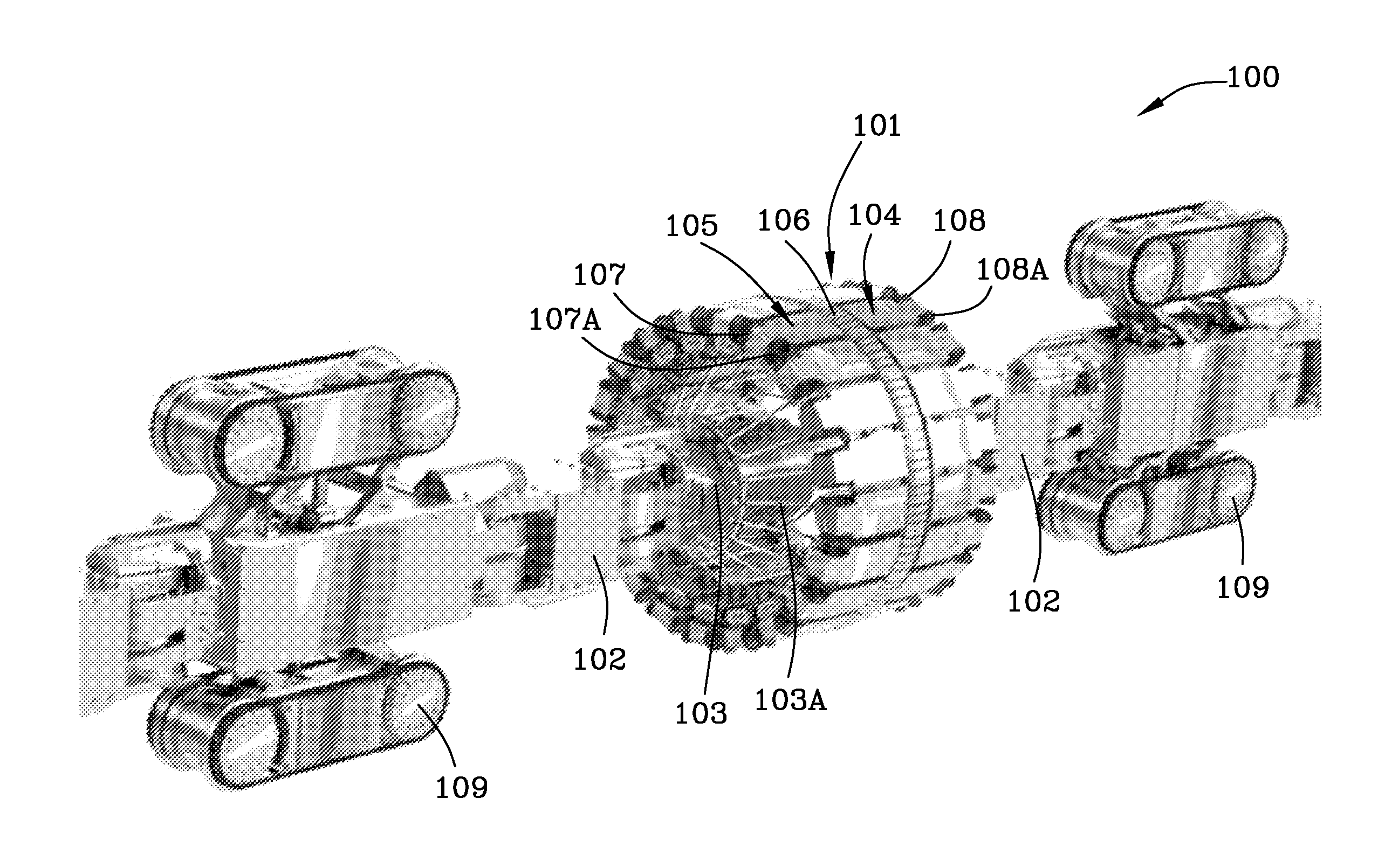
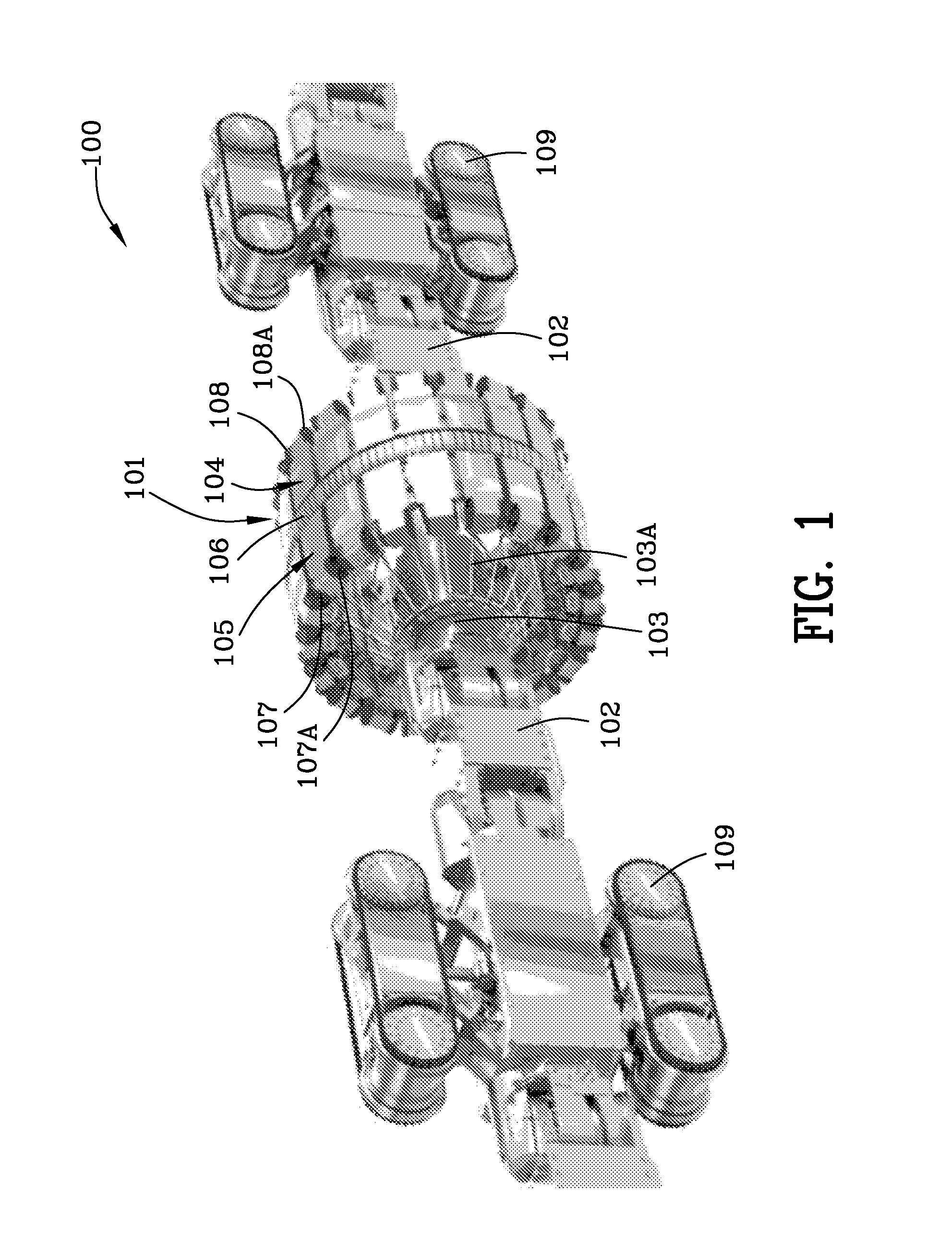
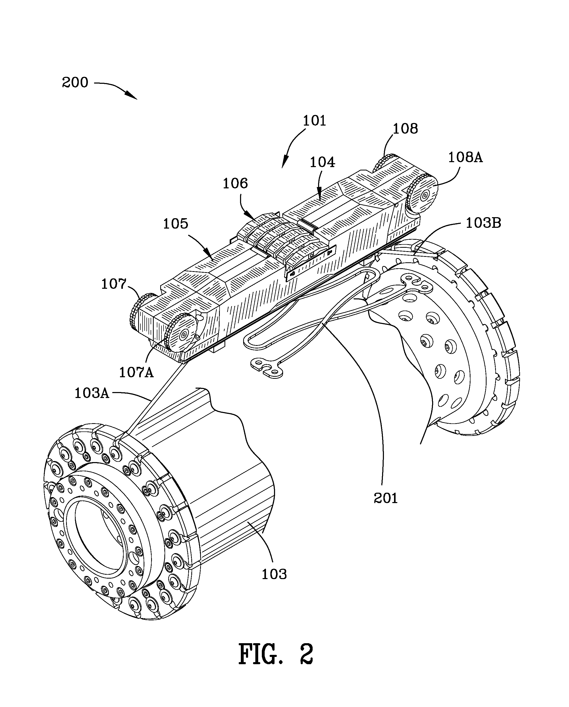
[0080]FIG. 1 is a schematic perspective view 100 of a plurality of conduit sensor devices 101, and, each of the conduit sensor devices 101 includes a plurality of sensors 106 and magnetic shunts. Arrow 101 is illustrated pointing to one conduit sensor with a magnetic shunt therein. Reference numeral 102 is used to denote couplings between the plurality of conduit sensors and battery powered drive units 109. A tubular radial control mechanism 103 controls wires / rods for extending the conduit sensors 101 radially outwardly and for contracting the conduit sensors radially inwardly. Arrow 104 indicates the second end of one conduit sensor with a magnetic shunt and arrow 105 indicates the first end of one conduit sensor with magnetic shunt. Arrow 106 indicates electronic sensors used to detect anomalies and defects in pipes and conduits. Reference numerals 107, 107A, 108, 108A denote rubber / synthetic propulsion wheels.
[0081]FIG. 2 is an enlargement 200 of a portion of FIG. 1 illustrating...
PUM
 Abstract
Description
Claims
Application Information
 - R&D
- Intellectual Property
- Life Sciences
- Materials
- Tech Scout
- Unparalleled Data Quality
- Higher Quality Content
- 60% Fewer Hallucinations
Browse by: Latest US Patents, China's latest patents, Technical Efficacy Thesaurus, Application Domain, Technology Topic, Popular Technical Reports.
© 2025 PatSnap. All rights reserved.Legal|Privacy policy|Modern Slavery Act Transparency Statement|Sitemap|About US| Contact US: help@patsnap.com


